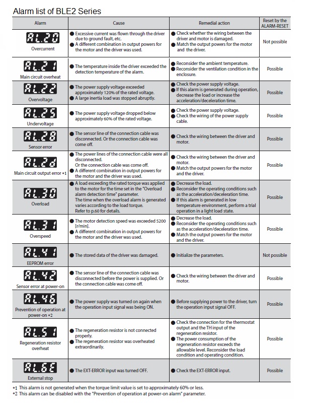
I am using the BLE2 Series, and I see the message 'AL30' on the front panel of the driver. What does AL30 mean?
''AL30' is an alarm indicating an overload condition.
The cause may be that a load exceeding the continuous operation range has been applied to the motor for more than the time set in the 'Overload alarm detection time' parameter.
Check the operating conditions such as load status, acceleration/deceleration time, etc.
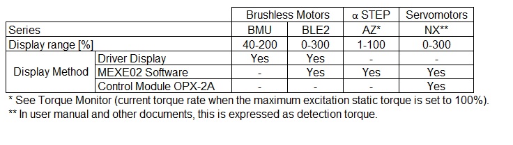
Is there a way to check the generated torque (load torque)?
It can be checked by the load factor.
The load factor is the ratio of the torque generated (load torque) to the motor's rated torque of 100%.
The method of checking depends on the product, please see below.
Can acceleration/deceleration be set in the BMU Series?
Acceleration and deceleration can be set in the following ways.
1) Analogue setting (default)
Remove the front cover and set the acceleration/deceleration time using the acceleration/deceleration time setter.
The setting range is 0.1 - 15.0 s.
2) Digital setting*
Set by operation data.
The setting range is 0.0 to 15.0 s. Settings can be made for each operation data No., and the acceleration time and deceleration time can be set respectively.
* When using digital settings, change the 'Analog acceleration/deceleration' parameter to 'Digital' beforehand.
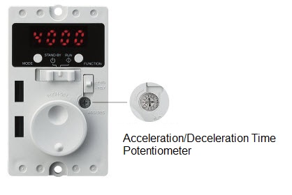
Figure 1
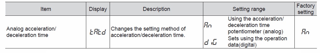
Figure 2
I changed the speed setting from 1000 rpm to 2000 rpm on the BMU Series, but when I switch the power back on and run the machine, it reverts to 1000 rpm. Why is this?
To confirm the changed speed, the setting dial must be pressed after changing the speed.
If the speed display is flashing, the speed has not been finalised, so press the setting dial at the end to finalise the speed.
The setting instructions are as follows:
1) Turn the dial to set the desired rotation speed (Fig. 1).
2) Press the dial to determine the rotation speed (Fig. 2).
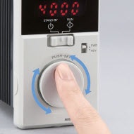
Figure 1
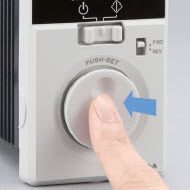
Figure 2
I am using the BLE2 Series. I would like to use two external speed-setting devices to change the speed in two steps, instead of using the internal speed-setting device, is this possible? Also, please tell me how to connect the wires in this case.
This is possible. The wiring is as follows.
Use a low-capacity contact type that can open and close 6 VDC 1 mA.
If a switch or similar with neutral contacts is used, the contacts will be open and the motor may result in a decelerating movement.
I want to run forward and reverse with an induction motor, how should I wire it up?
Induction motors are available in three-phase power input and single-phase power input types. The wiring method differs depending on the power supply voltage.
Three-phase motors
Three-phase induction motors rotate in the opposite direction when the two wires R, S or T in Fig. 1 are interchanged. Instantaneous forward and reverse rotation places a heavy load on the gears, resulting in gear damage and reduced service life. Switching the direction of rotation should be done after the motor has stopped.
Single-phase motors
Single-phase induction motors are available with three or four leads. With 3-lead motors, it is easy to rotate in the opposite direction by swapping the white and red wires on the L side, as shown in Fig. 2. When reversing an induction motor with four leads, it can be reversed by swapping the black and white wires. To do this, make the wiring as shown in Fig. 3. Single-phase induction motors with a large inertia load will not switch the direction of rotation when momentarily reversing forward or reverse. Switch the direction of rotation after the motor has stopped. If instantaneous forward/reverse operation is required during rotation, use a reversible motor.
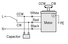
Figure 1
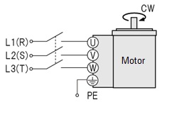
Figure 2
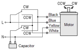
Figure 3
What is the difference between the READY output of the AZ Series and the PLS-RDY output?
The READY output is output when the driver is ready for operation.
The PLS-RDY output is output when the driver is ready for operation with pulse input.
The outputs SYS-RDY and DCMD-RDY are also available.
SYS-RDY output
The SYS-RDY output is issued when the state of the output signal is determined after power supply on and the signal input becomes effective.
DCMD-RDY output
This is output when the preparation for direct data operation is ready output.
Several products capable of network control are connected to the same master. If the support software MEXE02 is connected to the first unit, can data setting, teaching and remote operation other than on the first unit be possible?
This is not possible. For MEXE02, only one unit per file can be used for data setting and teaching/remote operation.
Can the AZ Series pulse input type be used with FREE input (motor non-excitation, electromagnetic brake release)?
This is possible. The FREE input operates even when the C-ON input is in the ON state (motor excitation ON).
When using the motor as the moving part, is it safe to use the connection cable in the cable holder?
Flexibility resistance differs considerably between connection cables and flexible connection cables. Therefore, if a connection cable is used in the cable holder, there is a risk of breaking the cable. Use flexible connection cables when used in moving parts.
I would like to carry out a 2-3 mm back-and-forth operation with the DR Series, DRS2 Series and DRLII Series, is this a problem in use?
There is no problem with 2-3 mm back-and-forth operation per se.
However, if the drive is a short distance, the grease may not circulate properly and the grease may be blank only in the part being used. Since insufficient grease can lead to failure, please ensure that the grease is circulated by, for example, running the machine at full stroke once a day.
Are electric cylinders capable of push-motion operation like air cylinders?
Push-motion operation is possible with the EAC series.
As the cylinder is equipped with a stepper motor, the force with which the load is pushed (pushing force) can be varied by changing the current value to the motor.
What is the difference between transportable mass and thrust force?
The transportable mass is the load mass that can be moved according to the specifications of the linear and rotary actuator. A value is set for the horizontal/vertical direction case respectively.
Thrust is the thrust force with which the linear and rotary actuator can propel the load. It is the force acting on the moving load.
With electric linear slides, is it possible to mount the sensor on the opposite side to the catalogue's dimensions?
This is possible. For installation, please confirm the product-specific operating manual.
Is it possible to change the motor cable outlet direction with electric linear slides?
It is possible to change the direction. Note, however, that this depends on the series and type. Please confirm details in the operating manual of each product. For some series the direction cannot be changed.
I want to use an electric linear slide to position a distance of 300 mm in 1 second. Can I select a product with a maximum speed of 300 mm/s? What should I consider the acceleration/deceleration time?
If you choose the maximum speed as it is, it will actually take longer. The maximum speed in the specification represents the instantaneous top speed of the linear slide and does not take acceleration/deceleration time into account. This means that it will actually take more time.
Although the exact takt time can be determined by calculation, our electric linear slides provide a positioning distance - positioning time diagram for each product for easy confirmation of the takt time.
What is the difference between the two units for rotation speed listed in the catalogue, [Hz] and [r/min]?
r/min represents the number of rotations per minute. This unit is commonly used to express the rotation speed of a motor.
Hz represents the number of pulses per second. This is the unit for the speed of the pulse signal fed from the controller to the control motor (driver). The pulse speed (Hz) is proportional to the rotation speed.
The conversion formula for [r/min] and [Hz] is as follows:
Rotation speed [r/min] = f × (θs/360) × 60
f : Pulse speed [Hz]
θs : Angle of movement per pulse of motor [˚]
During automatic sequencing of the AZ Series, the BREAK-ATSQ input was switched on to manual sequencing. How much time do I then need to take before the SSTART input?
When the BREAK-ATSQ input is switched ON and automatic progressive operation is switched to manual progressive operation:
(1) The motor standstill when the operation data currently in operation is finished.
Motor standstill can be confirmed by the READY output being switched ON.
(2) Once the READY output is switched ON, turn the SSTART input ON for at least 2 msec at the timing output after the simultaneous input (0 sec or more). 2 msec for the SSTART input is the time required for internal processing.
Can the HOME PRESET switch on the surface of the AZ Series driver be invalidated?
This is possible.
The signal assignment can be changed in the parameter 'Extended input (EXT-IN) function' in the parameter 'EXT-IN & VIR-IN & USR-OUT function (Extend)'.
The initial setting is 'P-PRESET', but if this is changed to "No function", the HOME PRESET switch on the front face of the driver is invalid.
Note that if a signal other than 'P-PRESET' is assigned to this parameter, the HOME PRESET switch can be changed to another function.
Is there a limit to the number of times the AZ Series of P-PRESETs can be used?
There is a limit on the number of times. When P-PRESET is executed, it is written to the driver's internal non-volatile memory, so the number of writable cycles is approximately 100 000.
What should I do if I want to return to the operation data of No. 0 in the middle of a manual progressive operation with the AZ Series?
By selecting operation data No. 0 and turning the START input ON, the machine returns to No. 0. Manual progressive operation can also be continued by turning the SSTART input ON.
Can the AZ Series switch to a different number of operation data during positioning mode signal triggered by some signal?
The event jump function enables switching of operation data. The event jump function is a function that causes the operation to be branched according to the ON/OFF of signals set in the 'Event trigger I/O' of the 'Operation I/O event'. If an 'Event trigger I/O' is detected during linked operation or loop operation, the operation is forcibly transitioned to the destination of the combined operation.
In the AZ Series built-in controller type, can industrial network control and direct input/output be used together?
Remote I/O and direct I/O via industrial network control or Modbus communication can be used together.
When the same input signals are assigned to remote I/O and direct I/O, the function is executed if either input is present.
The C-ON input* and HMI input** are always ON when not assigned to an input terminal.
When they are assigned to both remote I/O and direct I/O, they will not function unless both are switched ON.
*C-ON input: When switched on, the motor is excitation.
**HMI input : When switched on, the function restrictions of the support software MEXE02 are cancelled.
Is the 'Software overtravel' setting information of the AZ Series written to the motor or to the driver?
It is written to the driver.
Therefore, when replacing the driver, the parameter settings must be made again.
Not only the contents of the software overtravel, but also the data settings and parameter settings of the AZ Series are written to the driver. The only content that can be written to the motor is the home position setting by return-to-home operation or P-PRESET input.
In the AZ Series, what are the conditions under which the driver current control works when the content of the 'Current control mode' in the base setting parameter setting is set to 'Servo emulation (SVE)'?
If a deviation of 1 step or more occurs between the command position and the detection position, current control is triggered. The same applies when the 'Current control mode' content is set to 'Follow the CCM input' and the CCM input is switched on.