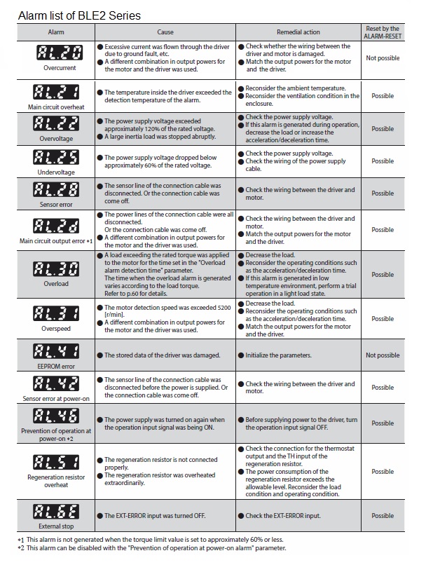
I am using the BLE2 Series, and I see the message 'AL30' on the front panel of the driver. What does AL30 mean?
'AL30' is an alarm indicating an overload condition.
The cause may be that a load exceeding the continuous operation range has been applied to the motor for more than the time set in the 'Overload alarm detection time' parameter.
Check the operating conditions such as load status, acceleration/deceleration time, etc.
Is there a way to check the generated torque (load torque)?
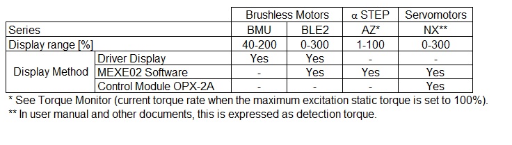
It can be checked by the load factor.
The load factor is the ratio of the torque generated (load torque) to the motor's rated torque of 100%.
The method of checking depends on the product, please see below.
Can acceleration/deceleration be set in the BMU Series?
Acceleration and deceleration can be set in the following ways.
1) Analogue setting (default)
Remove the front cover and set the acceleration/deceleration time using the acceleration/deceleration time setter.
The setting range is 0.1 - 15.0 s.
2) Digital setting*
Set by operation data.
The setting range is 0.0 to 15.0 s. Settings can be made for each operation data No., and the acceleration time and deceleration time can be set respectively.
* When using digital settings, change the 'Analog acceleration/deceleration' parameter to 'Digital' beforehand.
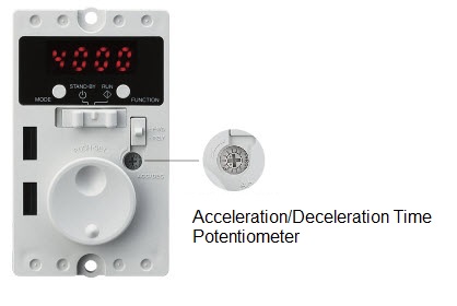
Figure 1
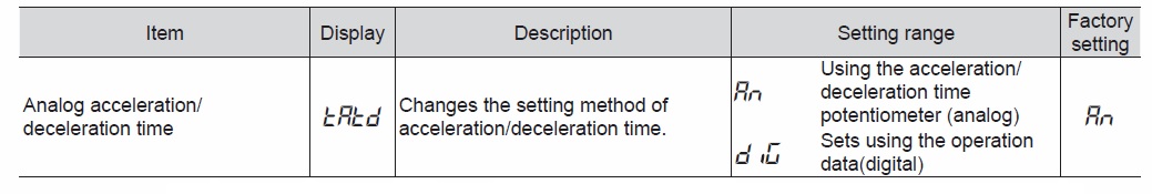
Figure 2
I changed the speed setting from 1000 rpm to 2000 rpm on the BMU Series, but when I switch the power back on and run the machine, it reverts to 1000 rpm. Why is this?
To confirm the changed speed, the setting dial must be pressed after changing the speed.
If the speed display is flashing, the speed has not been finalised, so press the setting dial at the end to finalise the speed.
The setting instructions are as follows:
1) Turn the dial to set the desired rotation speed (Fig. 1).
2) Press the dial to determine the rotation speed (Fig. 2).
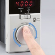
Figure 1
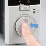
Figure 2
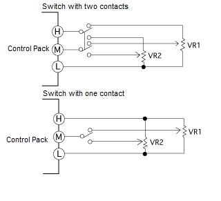
I am using the BLE2 Series. I would like to use two external speed-setting devices to change the speed in two steps, instead of using the internal speed-setting device, is this possible? Also, please tell me how to connect the wires in this case.
This is possible. The wiring is as follows.
Use a low-capacity contact type that can open and close 6 VDC 1 mA.
If a switch or similar with neutral contacts is used, the contacts will be open and the motor may result in a decelerating movement.
I want to run forward and reverse with an induction motor, how should I wire it up?
Induction motors are available in three-phase power input and single-phase power input types. The wiring method differs depending on the power supply voltage.
Three-phase motors
Three-phase induction motors rotate in the opposite direction when the two wires R, S or T in Fig. 1 are interchanged. Instantaneous forward and reverse rotation places a heavy load on the gears, resulting in gear damage and reduced service life. Switching the direction of rotation should be done after the motor has stopped.
Single-phase motors
Single-phase induction motors are available with three or four leads. With 3-lead motors, it is easy to rotate in the opposite direction by swapping the white and red wires on the L side, as shown in Fig. 2. When reversing an induction motor with four leads, it can be reversed by swapping the black and white wires. To do this, make the wiring as shown in Fig. 3. Single-phase induction motors with a large inertia load will not switch the direction of rotation when momentarily reversing forward or reverse. Switch the direction of rotation after the motor has stopped. If instantaneous forward/reverse operation is required during rotation, use a reversible motor.
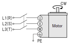
Figure 1
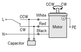
Figure 2
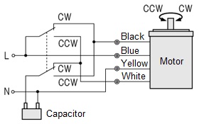
Figure 3
What are the conditions under which the TLC output of the AZ Series is switched on? Also, does the TLC output work in continuous operation (speed control) method as well as push-motion operation?
The conditions under which the TLC output is switched on depend on the current control mode, which is set in the parameter 'Current control mode'.
1) For 'Alpha control mode (CST)' (initial value)
(Including when the parameter setting is set to 'Follow the CCM input' and the CCM input is switched off.)
The TLC output is switched ON when the amount of deviation between command position and detection position is ±1.8° or more.
The command position and detection position are based on the position on the original motor shaft. They are not affected by the resolution being set, the geared type of the motor or the lead of the linear & rotary actuator.
2) For 'Servo emulation (SVE)' mode
(Including when the parameter setting is set to 'Follow the CCM input' and the CCM input is switched on.)
The TLC output is switched ON when the condition 1) is met and the motor current reaches the value of 'Operation current' in the operation data × 'Servo emulation (SVE) ratio' in the parameters.
Therefore, if the 'Servo emulation (SVE) ratio' is set to 0%, the TLC output works under the same conditions as in the Alpha control mode in 1).
The above ON conditions for the TLC output are common regardless of the type of operation, e.g. positioning operation or continuous operation.
Therefore, the TLC output turns ON under the same conditions when driven by the continuous operation (speed control) method.
Can the AC axial fans of the MRS Series be rotated in reverse?
This is not recommended as the fan blades are not designed for reversing.
Reversing is possible by changing the wiring, but blade efficiency is significantly reduced and the following problems may occur.
- The life of the winding is significantly affected by the temperature rise of the winding. In addition, the thermal protector may be activated.
- The blade fastening is designed in the normal direction of rotation. Reverse rotation may cause loosening of screws etc., resulting in a serious accident.
In the AZ Series, what are the conditions under which the driver current control works when the content of the 'Current control mode' in the base setting parameter setting is set to 'Servo emulation (SVE)'?
If a deviation of 1 step or more occurs between the command position and the detection position, current control is triggered. The same applies when the 'Current control mode' content is set to 'Follow the CCM input' and the CCM input is switched on.
When setting electronic gears using the MEXE02 with the AZ Series pulse-input type, does it matter whether function setting switch (SW1) No.1 on the front of the driver is turned to the ON or OFF side?
When setting the electronic gear, function setting switch (SW1) No. 1 must be turned to the OFF side. If it is turned to the ON side, the electronic gear setting is not reflected and the resolution is fixed at 10000 P/R.
I use gearheads, do I need to lubricate them?
Lubrication is not necessary.
Our gearheads are grease-lubricated. They are not designed to be dismantled.
Several products capable of network control are connected to the same master. If the support software MEXE02 is connected to the first unit, can data setting, teaching and remote operation other than on the first unit be possible?
This is not possible. For MEXE02, only one unit per file can be used for data setting and teaching/remote operation.
Can fans be driven in combination with inverters?
This is only possible for some three-phase power input type axial fans. Single-phase power input types cannot be driven in combination with inverters.
Can induction motors be run/stopped by SSRs (solid state relays)?
Running/stopping the motor and switching for forward/reverse rotation can be controlled by the SSR. However, please note the following two points:
1) Switching between running/stopping
As the motor is an inductive load, high voltages may be applied momentarily.
Select a SSR with a capacity of at least approximately twice the rated current.
2) Forward/reverse switching
Select a zero-crossing type SSR and provide a time lag of at least 30 msec when switching between forward and reverse signals.
For inductive loads such as motors, the current will try to continue to flow with a delay even after the voltage is switched off. Therefore, if no time lag is provided, the SSRs arranged for forward and reverse rotation will be switched on at the same time, resulting in a large current flow and possible damage to the SSRs.
Note that instantaneous forward and reverse rotation is not possible with induction motors.
Always switch between forward and reverse after the motor has stopped.
Can SSRs (solid state relays) be used for instantaneous forward and reverse rotation of reversible motors?
This is possible if a time lag of 30 msec or more is provided when reversing.
If instantaneous forward/reverse rotation is carried out without a sufficient time lag, the circuit may short-circuit due to the characteristics of the SSR.
Are electric cylinders capable of push-motion operation like air cylinders?
Push-motion operation is possible with the EAC series.
As the cylinder is equipped with a stepper motor, the force with which the load is pushed (pushing force) can be varied by changing the current value to the motor.
Can single-phase motors be driven by inverters?
No. Inverters are designed for three-phase motors.
Single-phase motors differ from three-phase motors in their operating principle and use a capacitor. Connecting a single-phase motor to the secondary side (output side) of the inverter may cause the capacitor to overheat or be damaged due to harmonic components.
Is there a way to check whether the main power is on in the AZ Series?
The main power is switched on if the red LED on the 'CHARGE' on the driver surface is illuminated. The LED may remain on for 5-10 minutes after the mains power is switched off, but will turn off when the internal residual voltage drops to a safe level.
Note that the MPS output can be used to check whether the main power is reliably switched on. The MPS output is switched on while the main power is switched on. The MPS outputs are not assigned by default, so the signal assignment must be changed. Use the support software MEXE02 to change the signal assignment.
An alarm occurred during execution of direct selection positioning operation (D-SEL input) on the AZ Series. After the motor has stopped, does the D-END output turn ON due to the alarm output function?
It turns ON.
The D-END output is switched ON when the motor stops after execution of the specified operation data setting, even if the motor stops before reaching the set travel amount due to a STOP input or alarm output, which is included in the conditions for the D-END output to be switched ON.
When confirming the completion of direct selection positioning operation, use the IN-POS output of the positioning mode signal in conjunction with the D-END output.
In the 'Operation method' setting of the AZ series operation data, there are 'Incremental positioning (based on command position)' and 'Incremental positioning (based on feedback position)', what is the difference between them?
The reference position at the start of operation for incremental positioning is different.
Inremental positioning (based on command position):
The driver operates with reference to the current command position, which is counted internally in the driver.
Incremental positioning (based on feedback position):
It operates with reference to the current feedback position of the mechanical absolute sensor (ABZO sensor) mounted at the rear of the motor.
What is the difference between the READY output of the AZ Series and the PLS-RDY output?
The READY output is output when the driver is ready for operation.
The PLS-RDY output is output when the driver is ready for operation with pulse input.
The outputs SYS-RDY and DCMD-RDY are also available.
SYS-RDY output
The SYS-RDY output is issued when the state of the output signal is determined after power supply on and the signal input becomes effective.
DCMD-RDY output
This is output when the preparation for direct data operation is ready output.
What is the difference between the two units for rotation speed listed in the catalogue, [Hz] and [r/min]?
r/min represents the number of rotations per minute. This unit is commonly used to express the rotation speed of a motor.
Hz represents the number of pulses per second. This is the unit for the speed of the pulse signal fed from the controller to the control motor (driver). The pulse speed (Hz) is proportional to the rotation speed.
The conversion formula for [r/min] and [Hz] is as follows:
Rotation speed [r/min] = f × (θs/360) × 60
f : Pulse speed [Hz]
θs : Angle of movement per pulse of motor [˚]
What is the difference between transportable mass and thrust force?
The transportable mass is the load mass that can be moved according to the specifications of the linear and rotary actuator. A value is set for the horizontal/vertical direction case respectively.
Thrust is the thrust force with which the linear and rotary actuator can propel the load. It is the force acting on the moving load.
What should I do if I want to return to the operation data of No. 0 in the middle of a manual progressive operation with the AZ Series?
By selecting operation data No. 0 and turning the START input ON, the machine returns to No. 0. Manual progressive operation can also be continued by turning the SSTART input ON.
What should be considered as a reference for rotational speed when gearheads are used with induction motors?
Induction motors are provided with a table in the catalogue entitled "Permissible torque" as a reference when gearheads are installed and used. Use a value 2-20% less than the rotational speed listed in this table as a guide.
The rotational speeds listed in the 'Permissible torque' are converted values obtained by dividing the synchronous rotational speed (50 Hz: 1500 r/min, 60 Hz: 1800 Hz/min) by the reduction ratio of the gearhead. The actual rotational speed is several percent lower than the synchronous rotational speed under no-load conditions and becomes even lower as the load increases.
The load torque applied to the induction motor is limited by the rated torque, which is approximately 1200 r/min (-20% of synchronous speed) at 50 Hz and 1500 r/min (-17% of synchronous speed) at 60 Hz.