Can the programmable controller confirm whether the AZ Series driver accepts the STOP input?
This can be confirmed by the driver's response output.
Take the 'STOP_R' output into the programmable controller.
Whether the motor actually stopped can be confirmed by the 'MOVE' output.
A response output is a signal that outputs the ON/OFF status of the corresponding input signal.
There is a pair of response outputs for all input signals, not just the STOP input (Output signal name: 'Input signal name_R').
What are the conditions under which the TLC output of the AZ Series is switched on? Also, does the TLC output work in continuous operation (speed control) method as well as push-motion operation?
The conditions under which the TLC output is switched on depend on the current control mode, which is set in the parameter 'Current control mode'.
1) For 'Alpha control mode (CST)' (initial value)
(Including when the parameter setting is set to 'Follow the CCM input' and the CCM input is switched off.)
The TLC output is switched ON when the amount of deviation between command position and detection position is ±1.8° or more.
The command position and detection position are based on the position on the original motor shaft. They are not affected by the resolution being set, the geared type of the motor or the lead of the linear & rotary actuator.
2) For 'Servo emulation (SVE)' mode
(Including when the parameter setting is set to 'Follow the CCM input' and the CCM input is switched on.)
The TLC output is switched ON when the condition 1) is met and the motor current reaches the value of 'Operation current' in the operation data × 'Servo emulation (SVE) ratio' in the parameters.
Therefore, if the 'Servo emulation (SVE) ratio' is set to 0%, the TLC output works under the same conditions as in the Alpha control mode in 1).
The above ON conditions for the TLC output are common regardless of the type of operation, e.g. positioning operation or continuous operation.
Therefore, the TLC output turns ON under the same conditions when driven by the continuous operation (speed control) method.
An alarm occurred during execution of direct selection positioning operation (D-SEL input) on the AZ Series. After the motor has stopped, does the D-END output turn ON due to the alarm output function?
It turns ON.
The D-END output is switched ON when the motor stops after execution of the specified operation data setting, even if the motor stops before reaching the set travel amount due to a STOP input or alarm output, which is included in the conditions for the D-END output to be switched ON.
When confirming the completion of direct selection positioning operation, use the IN-POS output of the positioning mode signal in conjunction with the D-END output.
In the 'Operation method' setting of the AZ series operation data, there are 'Incremental positioning (based on command position)' and 'Incremental positioning (based on feedback position)', what is the difference between them?
The reference position at the start of operation for incremental positioning is different.
Inremental positioning (based on command position):
The driver operates with reference to the current command position, which is counted internally in the driver.
Incremental positioning (based on feedback position):
It operates with reference to the current feedback position of the mechanical absolute sensor (ABZO sensor) mounted at the rear of the motor.
I use gearheads, do I need to lubricate them?
Lubrication is not necessary.
Our gearheads are grease-lubricated. They are not designed to be dismantled.
Can I combine my current induction motor (or reversible motor) with a speed control pack for speed control?
Induction motors and reversible motors are not possible. Speed control packs require an AC speed control motor with a built-in rate generator. The speed control pack uses feedback from the rate generator to detect the rotational speed and control the motor output.
Can induction motors be run/stopped by SSRs (solid state relays)?
Running/stopping the motor and switching for forward/reverse rotation can be controlled by the SSR. However, please note the following two points:
1) Switching between running/stopping
As the motor is an inductive load, high voltages may be applied momentarily.
Select a SSR with a capacity of at least approximately twice the rated current.
2) Forward/reverse switching
Select a zero-crossing type SSR and provide a time lag of at least 30 msec when switching between forward and reverse signals.
For inductive loads such as motors, the current will try to continue to flow with a delay even after the voltage is switched off. Therefore, if no time lag is provided, the SSRs arranged for forward and reverse rotation will be switched on at the same time, resulting in a large current flow and possible damage to the SSRs.
Note that instantaneous forward and reverse rotation is not possible with induction motors.
Always switch between forward and reverse after the motor has stopped.
Can single-phase motors be driven by inverters?
No. Inverters are designed for three-phase motors.
Single-phase motors differ from three-phase motors in their operating principle and use a capacitor. Connecting a single-phase motor to the secondary side (output side) of the inverter may cause the capacitor to overheat or be damaged due to harmonic components.
Can SSRs (solid state relays) be used for instantaneous forward and reverse rotation of reversible motors?
This is possible if a time lag of 30 msec or more is provided when reversing.
If instantaneous forward/reverse rotation is carried out without a sufficient time lag, the circuit may short-circuit due to the characteristics of the SSR.
I use a speed control motor with electromagnetic brake. Is a FREE input (or MB-FREE input) required to run or stop the motor?
The FREE input (or MB-FREE input)* is not required. The FREE input (or MB-FREE input) is a signal to release the electromagnetic brake when the motor is stopped and you want to move the load. To run or stop the motor, use the FWD input or REV input of the operation signal.
* Signal names:
DSC Series: FREE
BLE2 Series: MB-FREE
How can I check if a brushless motor (BMU Series, BLE2 Series, BXII Series) is broken?
You can check this in a simplified way as follows.
Check that all motor winding resistance values are the same.
1. Ensure that the driver is switched off and disconnect the motor cable from the driver.
2. Place a tester on the pins of the motor cable connector and measure the resistance at three points.
Between blue (U) and purple (V)
Between purple (V) and grey (W)
Between Grey (W) - Blue (U)
If the measured values are all the same resistance value, it is normal.
If the resistance values cannot be measured or if the values differ from each other, burnout or disconnection of the motor is suspected.
Note: If an extension cable is used, first take measurements with the extension cable connected.Then remove the extension cable and measure with the motor cable only.
Check if the driver LEDs light up.
With the motor cable connected, apply power to the driver and check that the display on the control panel and the CHARGE LED* lights up.
If the lights remain off after switching on the power, voltage may not be correctly applied to the power supply line.
Check the power supply voltage with a tester.
If the light remains off even if voltage is correctly applied, a driver failure is suspected.
* The BMU Series does not have a CHARGE LED. Check the display only.
If a product failure is suspected, please use our inspection and repair service (free inspection).
The brushless motor (BMU Series, BLE2 Series, BXII Series) does not rotate. Is there any way to check the cause of non-rotation?
If an alarm has occurred, take action according to the contents of the operating instructions.
If no alarms are present, check the following contents and refer to the relevant sections of the operating instructions.
The product is out of order.
- The motor or driver is faulty.
- The motor cable or extension cable is disconnected.
Wiring problems.
- The power supply is not connected or applied correctly.
- Input signals (FWD, RVS, START, etc.) are incorrectly wired or disconnected.
There is a problem with the parameter settings.
BMU Series:
- The operation method and the "External operation signal" parameter setting are different.
BLE2 Series:
- Operation method and "speed/torque limit command selection" parameter settings differ.
- The torque limit setting is low in relation to the load.
BXII Series:
- The operation method and the 'Analog speed/torque' parameter setting differ.
- The torque limit setting is low for the load.
There is a problem with the state of the input signal or the operating command.
BMU Series:
- Both FWD and RVS inputs are on or both are off.
- The operation switch is in the STAND-BY side.
BLE2 Series:
- Both FWD and RVS inputs are on or both are off.
- Either the START/STOP input or the RUN/BRAKE input is OFF.
- The local operation operation is being used incorrectly.
BXII Series:
- Both FWD and RVS inputs are on or both are off.
- Either the FREE input or the STOP input is ON.
- The S-ON input is assigned to an input terminal, but the S-ON input is OFF.
How to check the input signals
The ON/OFF status of input signals can be monitored on the driver itself for the BMU Series, BLE2 Series and BXII Series. For details, see the operating manual.
In the case of the BLE2 Series, the status can also be monitored by the support software MEXE02.
In the case of the BXII Series, it can also be monitored by the support software MEXE02 and the data setting unit OPX-2A.
If the AZ and AR series with electromagnetic brake are driven vertically, is it safe to release the electromagnetic brake as soon as the power is switched on?
Release the electromagnetic brake at least 0.5 sec after switching on the power. It takes up to 0.5 sec for the driver to complete initialisation (preparation for operation), so if the electromagnetic brake is released before this time, the workpiece may fall.
What is the delay time for phase A (ASG) pulse output and phase B (BSG) pulse output?
The delay time for phase A pulse output and phase B pulse output for AZ Series, AR Series and NX Series is max. 100 µsec or less.
When stopping an AZ or AR Series type with an electromagnetic brake during operation, can the motor be stopped by switching off the C-ON input?
Do not use the C-ON input to stop the motor. The reason depends on the model used, as follows.
AZ Series, as well as ARD-A(D), ARD-C(D), ARD-S and ARD-KD*
If the C-ON input is switched OFF during operation, the electromagnetic brake is activated while the motor is running. The excitation is then switched off and the motor drags the electromagnetic brake to a final stop.
The electromagnetic brake is thus designed to engage before the motor excitation is switched off. This is to prevent the workpiece from falling if the C-ON input is switched off when the machine is stopped, by activating the electromagnetic brake first.
This means that the purpose of the electromagnetic brake used in the AZ and AR Series is solely to hold the workpiece in place when the motor is stopped, and is different in construction from a braking electromagnetic brake with brake linings.
Therefore, forcing a motor with inertia to be stopped by friction can put a strain on the brake section, affecting its service life or, in the worst case, damaging it.
ARD-K*
Electromagnetic brakes are externally controlled (e.g. by a programmable controller or other external power source). Therefore, if a control is set up to activate the electromagnetic brake immediately after the C-ON is switched off, the same problem as above can occur.
Alternatively, if the sequence does not activate the electromagnetic brake even after the C-ON is switched off, the motor without holding power will not be able to maintain its position. Especially in the case of vertical drives, the workpiece will fall.
When a workpiece is dropped, the motor becomes a generator and back EMF is applied to the driver.
The back EMF (regenerative voltage) at this time increases with distance and speed, which in some cases may cause an overvoltage alarm in the driver, and in the worst case may damage the driver.
* ARD-...(D) is the AR Series driver name.
What is the resolution of the ASG/BSG outputs of the AZ Series?
This depends on the resolution setting of the motor output axis, which is set when the control power supply is switched on. The default setting is 1000 P/R.
When setting electronic gears using the MEXE02 with the AZ Series pulse-input type, does it matter whether function setting switch (SW1) No.1 on the front of the driver is turned to the ON or OFF side?
When setting the electronic gear, function setting switch (SW1) No. 1 must be turned to the OFF side. If it is turned to the ON side, the electronic gear setting is not reflected and the resolution is fixed at 10000 P/R.
What should be considered as a reference for rotational speed when gearheads are used with induction motors?
Induction motors are provided with a table in the catalogue entitled "Permissible torque" as a reference when gearheads are installed and used. Use a value 2-20% less than the rotational speed listed in this table as a guide.
The rotational speeds listed in the 'Permissible torque' are converted values obtained by dividing the synchronous rotational speed (50 Hz: 1500 r/min, 60 Hz: 1800 Hz/min) by the reduction ratio of the gearhead. The actual rotational speed is several percent lower than the synchronous rotational speed under no-load conditions and becomes even lower as the load increases.
The load torque applied to the induction motor is limited by the rated torque, which is approximately 1200 r/min (-20% of synchronous speed) at 50 Hz and 1500 r/min (-17% of synchronous speed) at 60 Hz.
The absolute position that can be detected by the AZ series is in the range -900 to +900 revolutions, but will it still work if rotated beyond that range?
It will move even beyond the range of -900 to +900 revolutions without resulting in an alarm. However, if -900 to +900 revolutions are exceeded, the current position counted inside the product will change as follows. The following explanation uses the case of 1000 steps per revolution (factory resolution) as an example.
When exceeding +900 revolutions
+8999999 step is followed by -900000 step
When exceeding -900 revolutions
-900000 step is followed by +8999999 step
The RND-OVF output is switched on when the -900 to +900 rpm range is exceeded. The RND-OVF output is switched off when the power is switched on again.
Note:
- The RND-OVF output only functions when the Round (RND) setting parameter is enabled. When the Round (RND) setting parameter is disabled, the RND-OVF output does not function and will not turn on beyond the -900 to +900 rpm range.
- For AZ14, AZ15, AZ24 and AZ26 types, the absolute position ranges from -450 to +450 rpm.
Can I check the motor temperature of the AZ Series?
The motor temperature can be checked using 'Status Monitor' in the support software MEXE02.
The motor temperature is measured by the ABZO sensor inside the motor. To protect the ABZO sensor, a motor overheat alarm is output if the detected temperature rises above 85 °C.
Note that the information function can be used to change the detection temperature setting. Use the parameter 'Motor temperature information (INFO-MTRTMP) [°C]' in the MEXE02 parameter 'ETO & Alarm & Info' to make the setting.
In the AZ Series, can two items be set in the reflection trigger for direct data operation?
One item can be set, but not two items. To set two or more multiple items, such as position and speed, the method is to rewrite all items at once.
Is it possible to display the position of AZ Series motors in mm on the touch screen?
It can be displayed by using FA network control or Modbus (RTU) RS-485 communication. When FA network control or Modbus (RTU) RS-485 communication is used, the units for command position and feedback position are output in 'step', so please perform the conversion on the touch panel or programmable controller.
Is there a way to check whether the main power is on in the AZ Series?
The main power is switched on if the red LED on the 'CHARGE' on the driver surface is illuminated. The LED may remain on for 5-10 minutes after the mains power is switched off, but will turn off when the internal residual voltage drops to a safe level.
Note that the MPS output can be used to check whether the main power is reliably switched on. The MPS output is switched on while the main power is switched on. The MPS outputs are not assigned by default, so the signal assignment must be changed. Use the support software MEXE02 to change the signal assignment.
The computer went into sleep mode when the AZ Series and the support software MEXE02 were connected. Why does data readout fail when I start up again?
This is because entering sleep mode disconnects the USB.
Unplug and re-plug the USB or re-configure the communication port settings on the MEXE02.
If the problem persists after reconnecting, restart the MEXE02 and read out the data.
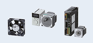
Is there a way to inform that the fan motor has stopped?
Our axial fans are available with a built-in alarm circuit that alerts the user to an abnormality if the fan's blowing capacity is reduced or if the fan stops.
Low speed alarm
An alarm is output when the rotation speed of the fan motor decreases due to life or contamination by foreign matter.
The low rotation can be detected so that arrangements can be made and replaced before the fan motor stops.
Stop sensor
An alarm is output when the fan motor stops.
The fault stoppage can be detected immediately and the relevant fan motor can be replaced.