Structure of stepper motors
The cross section of a stepper motor is shown in Fig. 1 below. A stepper motor consists of two main parts: the stator and the rotor.
The rotor consists of three parts: rotor 1, rotor 2 and permanent magnet. The rotor is magnetised in axial direction, with rotor 1 having an N pole and rotor 2 having an S pole.
The stator has magnetic poles with small teeth, each with its own winding.
The windings are connected at opposite magnetic poles and are wound in such a way that they are magnetised to the same polarity when current is applied. This means that when current is applied to a winding, the opposite magnetic poles are magnetised to the same polarity, e.g. N-pole or S-pole.
The two magnetic poles opposite each other form one phase: the type with five phases from phase A to phase E is called a 5-phase stepper motor, while the type with two phases, phase A and phase B, is called a 2-phase stepper motor.
There are 50 small teeth on the outside of the rotor, with the small teeth of Rotor 1 and Rotor 2 mechanically displaced by half a pitch.
Excitation state: the state in which current flows through the motor windings.
Magnetic pole: a protruding part of the stator that becomes electromagnetised by excitation.
Small teeth: the teeth of a rotor or stator.
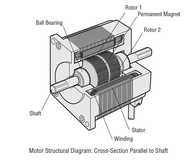
Figure 1
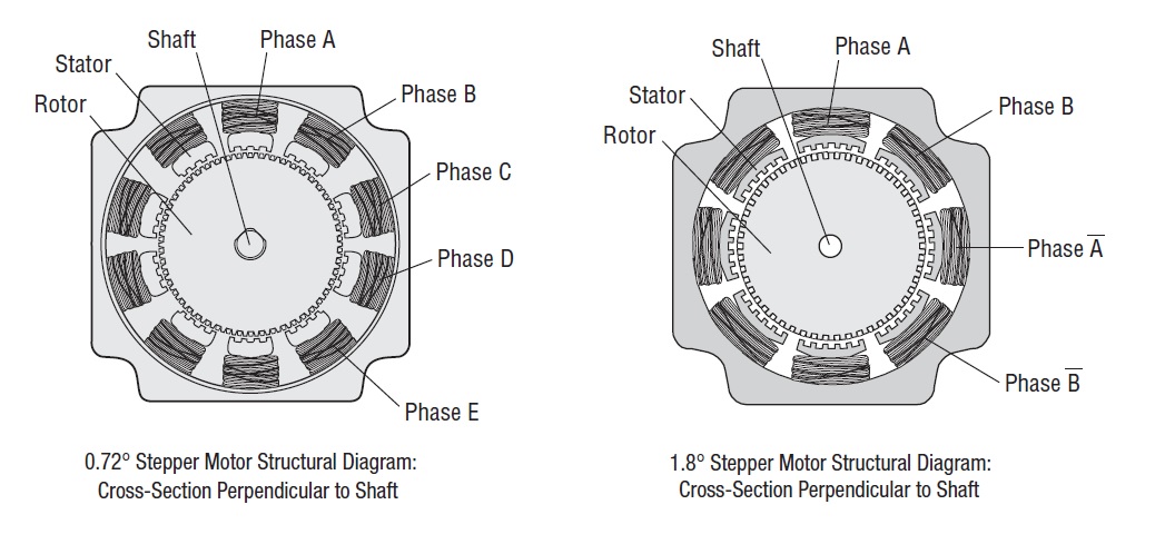
Figure 2
Operating principle of stepper motors
The positional relationship between the stator and the small teeth of the rotor in the case of actual magnetisation is described using a 5-phase stepper motor as a practical example.
When phase A is excited (Fig. 1)
When phase A is excited, the magnetic poles are magnetised to the S-pole, attracting the small teeth of rotor 1, which have an N-pole polarity, and repelling and balancing the small teeth of rotor 2, which have an S-pole polarity, to a stop. The small teeth of the magnetic pole of phase B, which is not excited, are 0.72° out of alignment with the small teeth of rotor 2, which has an S-pole polarity. This is the positional relationship between the small teeth of the stator and rotor when phase A is excited.
When phase B is excited (Fig. 2)
Next, when switching from phase A excitation to phase B excitation, the magnetic poles of phase B are magnetised to the N poles, attracting rotor 2, which has S polarity, and repelling rotor 1, which has N polarity.
This means that switching the excitation phase from phase A excitation to phase B excitation rotates the rotor by 0.72°. As can be seen, by switching the excitation phase from phase A to phase B to phase C to phase D to phase E to phase A, the stepper motor rotates precisely by 0.72°. If rotation in the opposite direction is required, this can be achieved by reversing the excitation order: phase A, phase E, phase D, phase C, phase B, phase A.
The high resolution of 0.72° is achieved due to the mechanical misalignment of the stator and rotor structure, which is why accurate positioning is possible without the use of encoders or other sensors. Also, the stopping accuracy is only limited to variations in the stator and rotor's finishing accuracy, assembly precision and the DC resistance of the windings, which is why a high stopping accuracy of ±0.05° (under no load) can be achieved. In an actual stepper motor, the driver is responsible for switching the excitation phase and the pulse signal input signal to the driver is responsible for the switching timing. This is an example of 1-phase excitation, but in reality 4-phase or 5-phase excitation is used simultaneously to make effective use of the windings.
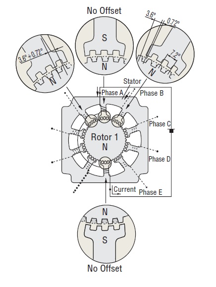
Figure 1
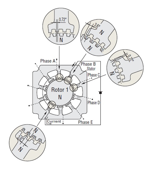
Figure 2
Basic characteristics of stepper motors
When using stepper motors, it is important to note whether the motor characteristics are suitable for the operating conditions. This section provides a description of the characteristics that are important when using stepper motors. The characteristics of stepper motors can be classified into two main categories.
Dynamic characteristics:
Characteristics related to the starting characteristics or rotation of the stepper motor, mainly related to the device's operation and cycle time.
Static characteristics:
Characteristics relating to the change in angle when the stepper motor is stopped and related to the accuracy of the device.
Dynamic characteristics
Speed-torque characteristics (Fig. 1)
This characteristics diagram shows the relationship between speed and torque characteristics when driving a stepper motor.
These characteristics are always used when selecting a stepper motor. The horizontal axis represents the speed of the motor output shaft and the vertical axis represents torque.
The speed-torque characteristic is determined by the motor and driver and varies greatly depending on the product line used.
(1) Excitation maximum holding torque (TH: Holding Torque)
The maximum holding torque (holding force) that a stepper motor has when it is stopped in energised condition (rated current).
(2) Pullout Torque
The instantaneous maximum torque that can be produced at each rotational speed. When selecting a motor, the required torque must fall within this curve.
(3) Maximum self-starting frequency (fS)
The maximum pulse speed at which a stepper motor can start and stop instantaneously (without acceleration/deceleration time) when the frictional load and inertia load are zero.
If the motor is driven at a higher pulse speed, it must be gradually accelerated and decelerated. This frequency is subject to deterioration as an inertia load is attached to the motor. (See inertia load - starting frequency characteristics).
Maximum response frequency (fr)
This is the maximum pulse speed at which a stepper motor can be operated by gradual acceleration and deceleration when the frictional load and inertia load are zero. Fig. 2 shows the rotation speed-torque characteristics of a typical 5-phase stepper motor.
Inertia load - starting frequency characteristics (Fig. 3)
This characteristic represents the change in starting frequency due to inertia load.
The rotor inertia moment of the stepper motor itself and the load causes the motor shaft to lag or advance during instantaneous start and stop. This value varies according to the pulse speed, but if it exceeds a certain value, the motor will not be able to follow-up the pulse speed and will step out (misstep).
The pulse speed just before misstep is called the starting frequency.
The variation of maximum starting frequency with respect to inertia load can be approximated by the formula shown in Fig. 4.
Vibration characteristics
Stepper motors rotate in a continuous step-like motion. The single-step response in Fig. 5 shows one of these step-like movements.
(1) When one pulse is input to a stopped stepper motor, it accelerates towards the next step angle.
(2) The accelerated motor passes through the step angle, overshoots a certain angle and then pulls back in the opposite direction.
(3) After damped oscillation in this manner, the motor stops at the predetermined step angle position.
This step-like movement, which produces damped oscillations, is the cause of low speed oscillations.
The vibration characteristics in Fig. 6 express the magnitude of vibration during rotation of a stepper motor. The lower the vibration level, the smoother the rotation.
Static characteristics
Angle-torque characteristics
The relationship between the angle and torque when the motor is excitation current rated and torque is applied externally to the motor shaft to give the rotor an angle change is called the angle-torque characteristic and is shown in Fig. 7.
The position of the stator and small teeth of the rotor at each point in the characteristics diagram above is shown in Fig 8.
When the motor standsstill balanced at stable point (1), if an external force is applied to the motor shaft, torque T (+) is generated in the left side to pull it back to stable point (1) and it stops at an angle balanced with the external force. (2)
If an external force is applied further, there is an angle at which the generated torque reaches its maximum. The generated torque at that time is the maximum excitation static holding torque TH. (3) If an external force exceeding this is applied, it passes through unstable point (5), generates torque T (-) in the same direction as the external force, travels to the next stable point (1) and stops.
Stable point
This is the stop position where the small teeth of the stator and rotor stop in a perfectly relative position. It is very stable and always stops at this point when the external force is reduced to zero.
Unstable point
Refers to a location where the small teeth of the stator and rotor are off by half a pitch. It is very unstable and will move to the right or left stable point if any external force is applied.
Angular accuracy
Stepper motors have an angular accuracy of within ±0.05° in no load condition. The slight errors are caused by variations in the mechanical precision of the stator and rotor and the minute resistance of the stator windings.
The following stop position angle errors are commonly used to describe the angular accuracy of stepper motors.
Stop position error (Fig. 9)
This is the position error between the theoretical and actual stop position of the rotor. It is the width between the maximum value of (+) and the maximum value of (-) when the rotor's arbitrary stop position is taken as the starting point and measured 360° by one step.
The stop position error is within ±0.05°, but this value is based on no load conditions. In actual applications, however, there is always a frictional load.
The angular accuracy in such cases is based on the angle-torque characteristic, which results in angular displacement in accordance with the frictional load. If the frictional load is constant, the displacement angle is constant in unidirectional operation, but when operating in both back-and-forth operation, the displacement angle is twice as large in back-and-forth operation (Fig. 10).
If stopping accuracy is required, be sure to carry out positioning in one direction.
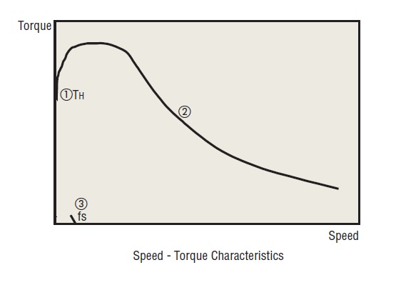
Figure 1: Speed-torque characteristics
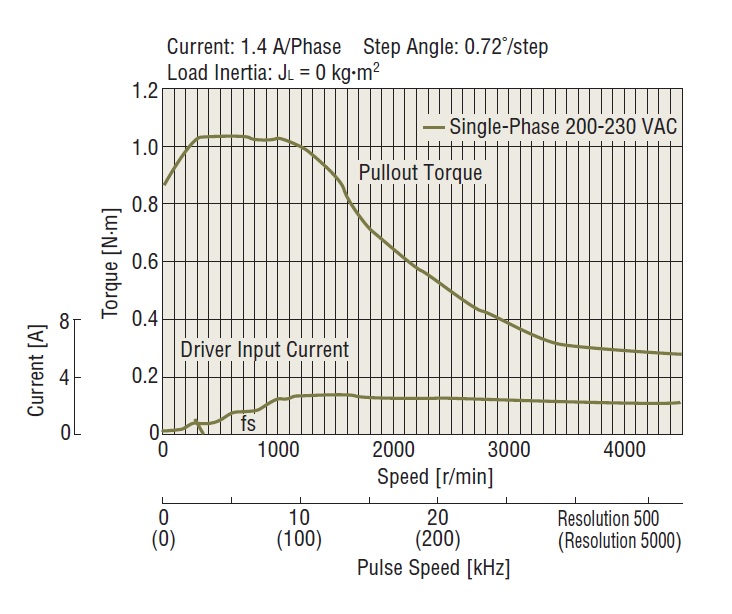
Figure 2: Speed-torque characteristics of a 5-phase stepper motor
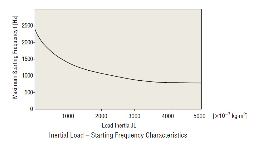
Figure 3: Inertia load - starting frequency characteristics
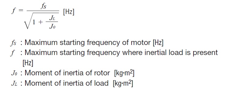
Figure 4: Formula for calculation the variation of the maximum starting frequency with respect to inertia load
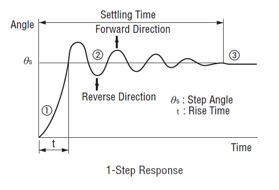
Figure 5: Response
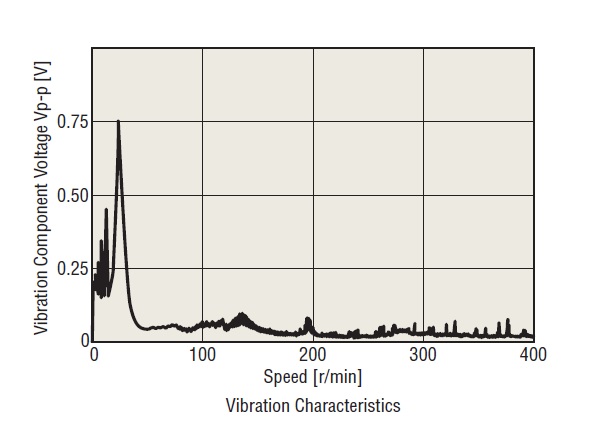
Figure 6: Vibration characteristics
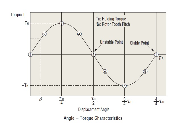
Figure 7: Angle-torque characteristics
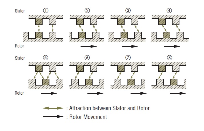
Figure 8: Teeth position of stator and rotor
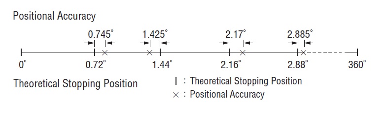
Figure 9: Stop position error
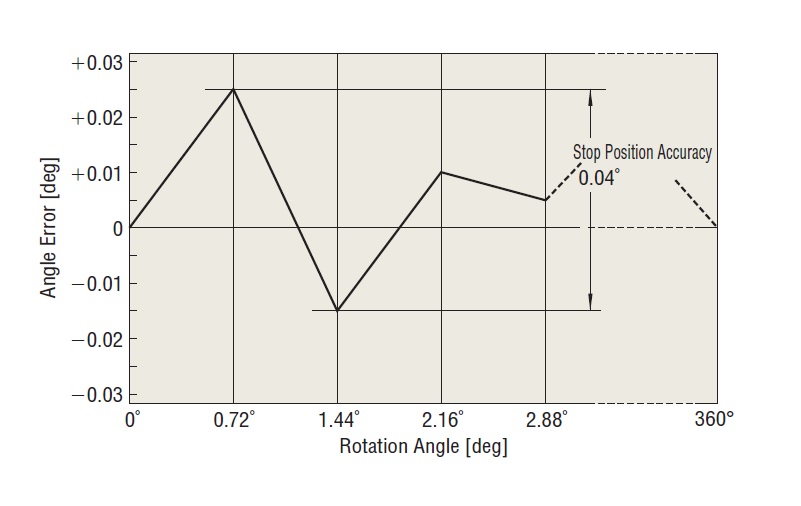
Figure 10
5-phase stepper motors
The 5-phase stepper motor and driver combinations presented on the website all consist of a 5-lead wire motor with new pentagon wiring and a driver with a dedicated excitation sequence. This unique combination enables:
- Easy wiring of the five leads
- Low vibration
The wiring and excitation sequence are described here.
New Pentagon wiring 4-phase excitation mode – full step
0.72°/step (Fig. 1)
The unique 5-phase motor excitation mode, which always excites 4-phase at a time, is 0.72° per step. The high damping effect ensures stable operation.
New Pentagon wiring 4-phase to 5-phase excitation mode – half step
0.36°/step (Fig. 2)
Alternating 4-phase excitation and 5-phase excitation mode, 0.36° per step.
One rotation can be divided into 1000 segments.
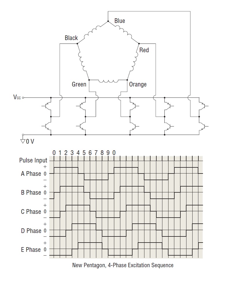
Figure 1
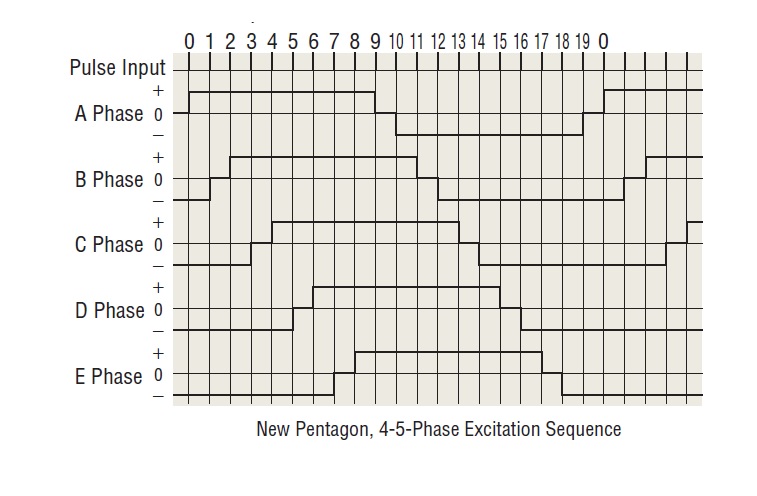
Figure 2
Stepper motor drivers
There are two drive systems for stepper motors: constant current drive system and constant voltage drive system.
The constant voltage drive system has a simple circuit configuration, but it is difficult to obtain torque characteristics in the high-speed range.
On the other hand, the constant current drive system is a drive system that is widely used today and features excellent torque characteristics in high-speed areas. All Oriental Motor drivers for stepper motors use this drive system.
Constant current drive systems
Stepper motors are rotated by switching the current in each winding in turn, but as the rotation speed increases, this switching becomes faster and the rise in current cannot keep up, resulting in a loss of torque.
By chopping a DC voltage much higher than the motor's rated voltage, the motor can be supplied with its rated current even at high speeds (Fig. 1 and 2).
The current flowing in the motor winding is extracted as a voltage by a current sensing resistor and compared with a reference voltage. When the voltage of the detection resistor is lower than the reference voltage (when the rated current is not reached), switching transistor Tr2 is continuously switched ON, and when the voltage is higher than the reference voltage (when the rated current is exceeded), Tr2 is switched OFF and the current is controlled so that the rated current always flows.
Differences in characteristics between AC and DC input (Fig. 3)
Stepper motors are driven by DC voltage applied via a driver.
In the case of our 24 VDC input products, 24 VDC is applied to the motor, while in the case of 100 VAC and 200 VAC input products, rectification to DC is performed once and approximately 140 VDC is applied to the motor (excluding some products).
The difference in the applied voltage to the motor is manifested in the difference in torque characteristics in the high-speed range. This is because the higher the applied voltage, the faster the rise of current in the motor wire, allowing the motor rated current to flow even in the high speed range. This means that AC input products have excellent torque characteristics throughout the entire range, from low speed to high speed, and a large speed ratio can be achieved.
When using the AC input products, we recommend that you first use products that can be adapted to the various operating conditions of the device.
Microstep technology
The basic step angle of 0.72° of a 5-phase stepper motor can be further divided into smaller steps (maximum 250) without any mechanical speed reduction mechanism.
Features
Stepper motors rotate and stop at each step angle determined by the salient-pole structure of the rotor and stator, so they feature high accuracy and easy position control. Conversely, however, rotation at each step angle causes speed changes in the rotor, which can lead to resonance and increased vibration characteristics at a certain number of rotations.
Microstep drive is a technology that realises ultra-low speed and noise reduction operation by subdividing the basic step angle of the motor by controlling the current that flows through the motor coil.
- The basic step angle of the motor (0.72°/full step) can be subdivided into 1/1 - 1/250, allowing smooth operation with minute angle feed.
- The technology for smoothly varying the motor drive current suppresses motor vibration and realises low noise operation.
Characteristics
- Low vibration (Fig. 4)
Microstep technology subdivides the step angles electrically. This smoothes out the step movements in the low speed area and significantly improves vibration.
Normally, dampers are used to reduce vibration, but the motor itself is designed for low vibration and the microstep technology further reduces vibration.
This greatly simplifies vibration measures, making it ideal for vibration-sensitive applications and equipment.
- Noise reduction
Microstep technology also improves vibration noise in low speed areas, resulting in low noise reduction. This is a powerful tool in noise-sensitive environments.
- Improved control (Fig. 5)
It is a new pentagonal microstep drive system with good damping characteristics.
Overshoots and undershoots at each step are minimal, and the drive follows-up the pulse pattern precisely (linearity is also improved. It also reduces shocks on start and stop.
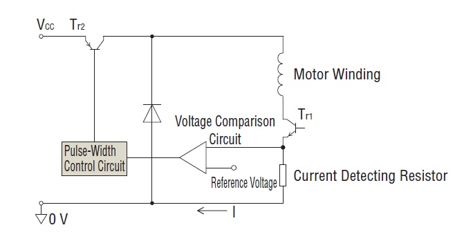
Figure 1
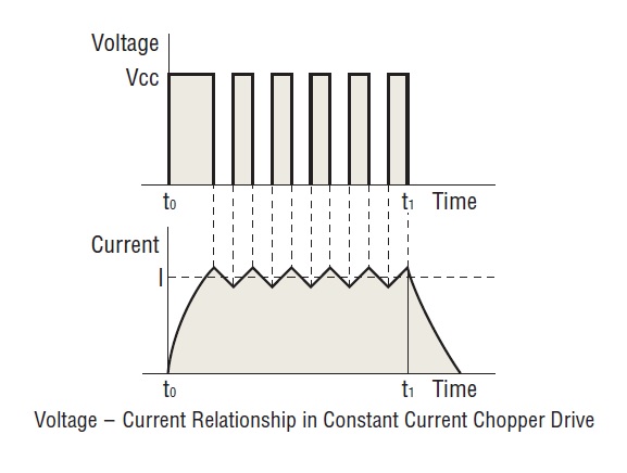
Figure 2
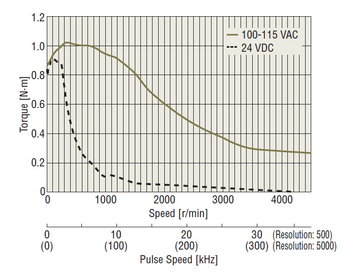
Figure 3
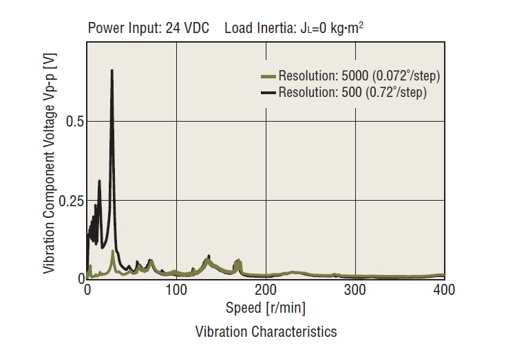
Figure 4
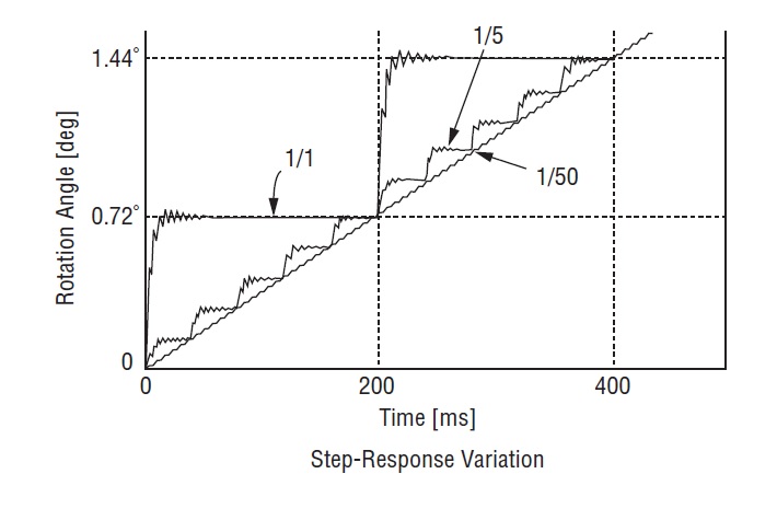
Figure 5
Alpha Step (αSTEP)
αSTEP is a stepper motor-based motor with a unique control system that hybridises the advantages of "open loop control" and "closed loop control". Under normal conditions, open loop control ensures high responsiveness. In the event of an overload, closed loop control is used to compensate for the motor position while the operation continues.
Use of closed loop control
A deviation counter calculates the deviation (time lag/advance) of the actual rotor rotation position from the command position of the pulse signal.
The deviation counter's calculation results are used to determine the 'overload duty region' and to switch between open mode and closed loop mode control for operation (Fig. 1).
- In normal operation, the unit operates in open mode.
- In the event of an overload, the unit operates in closed loop mode.
In closed loop mode, the excitation state of the motor winding is controlled so that the instantaneous maximum torque is generated for the rotor rotation position control.
This control method ensures that there is no unstable point (overload area) in the angle-torque characteristics (Fig. 2).
AZ Series
Mechanical multi-turn absolute sensor (ABZO sensor)
The ABZO sensor (Fig. 3) mechanically detects position and stores the position on the sensor side. By storing position information at the sensor side, an absolute system can be constructed that can hold position information even when the power supply is shut down. In addition, the batteries conventionally required to back up position information are no longer necessary, and position is not lost even if the motor cable is disconnected.
AR Series
Built-in rotor position detection sensor
A rotor position detection sensor is built-in on the opposite output shaft side of the motor (Fig. 4).
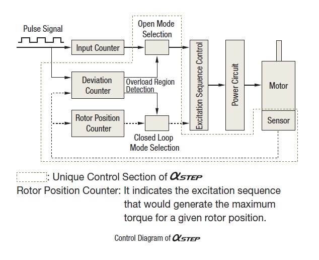
Figure 1
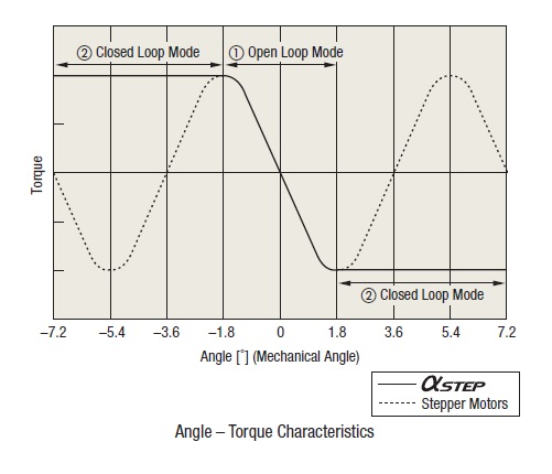
Figure 2
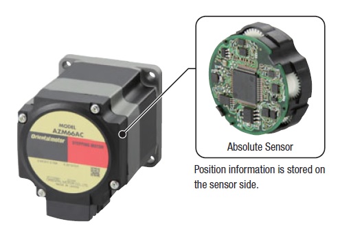
Figure 3
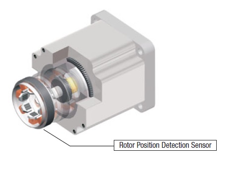
Figure 4
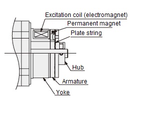
Structure and lifetime of the electromagnetic brake of stepper motors
The electromagnetic brake motor uses a non-excitation activated type electromagnetic brake for position holding. An example structure is shown in the structural drawing below.
When voltage is applied to the excitation coil, an electromotive force in the opposite direction to the magnetic force of the permanent magnet is generated, which releases the armature by the force of the disk spring and the brake is released, freeing the motor shaft from rotation.
When no voltage is applied, the armature adsorbs the yoke by means of permanent magnets and the motor shaft is fixed.
Operation and lifetime
This brake can be used for holding the position when the motor is not excited. Do not use it for braking to stop a rotating load. As the brake is not equipped with a brake lining, repeated braking will cause metal-to-metal rubbing and wear and seizure, resulting in failure to operate normally.
The operating life is one million cycles due to the fatigue life of the plate spring.
As the stepper motor has a holding force when stopped, the electromagnetic brake is only intended for use when the equipment is switched on and off.
Stepper motors in environments above 1000 m above sea level
At higher altitudes, the effectiveness of atmospheric heat dissipation is reduced, so it is necessary to take measures such as lowering the ambient temperature of the product. Below are the conditions for use at altitudes above 1000 m and below 2000 m above sea level.
Eligible products
- AZ Series, AR Series
- PKP Series, PK Series
- CRK Series
- CVD Series
- RKII Series
Conditions of motor use
If the motor is used above 1000 m and below 2000 m above sea level, the surface temperature of the motor case must not exceed the following values:
AZ Series: 80°C*
AR Series: 100°C*
RKII Series: 100°C (85°C**)
CRK Series: 100°C (85°C**)
PKP Series: 100°C (85°C**)
PK Series: 100°C (except with encoder)
* When obtaining the UL standard, the heat resistant class of the motor part is Class A, so please do not exceed 75°C.
** Values in () are values with encoder.
Conditions of driver use
If the motor is to be used above 1000 m above sea level and below 2000 m, lower the ambient temperature as shown in Figure 1.
For example, if a product with an upper ambient temperature limit of 40°C is used at 2000 m above sea level, the upper ambient temperature limit is 32°C.
When using geared motors
Please use it in a range less than 2000 m above sea level. If the altitude becomes high, then the temperature rise due to the difference between the outside air pressure and the heat dissipation will decrease the life of the oil seal and grease leakage inside the gearhead may occur. If grease leakage becomes a problem, periodically check for bleeding of the grease, attach the oil pan etc. to the equipment.

Figure 1
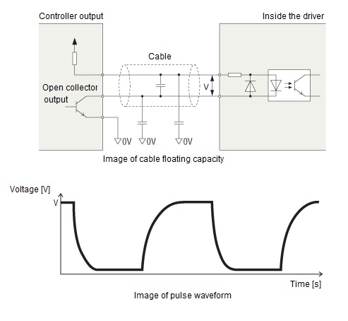
Relationship between cable length and transmission frequency for stepper motors
The longer the pulse line, the lower the highest frequency that can be transmitted.
This is due to the effect of the resistance component and stray capacitance of the cable, which forms a CR circuit and delays the rise and fall of the pulse.
The stray capacitance of cables occurs between wires and between wires to ground. It is difficult to give a clear figure because conditions vary depending on the type of cable, wiring, routing, etc.
Structure and operation principle of brushless motors
Structure of brushless motors
The construction of brushless motors is such that a magnetic element for detecting the position of the rotor or an optical encoder is built into the motor. This position detector sends a signal to the drive circuit. The motor windings are three-phase star-connected. The rotor also uses permanent magnets. See Fig. 1 and 2.
Hall ICs are used as the magnetic elements for detection. Three of these are located inside the stator and a digital signal is output from the Hall IC each time the rotor rotates.
Brushless motor drive methods
Switching transistors are connected to the motor windings and six transistors form an inverter. The upper and lower transistors are alternately switched on and off in a fixed sequence to change the direction of the winding current. This section explains how it rotates.
In step (1) in the switching sequence of the transistors in Fig. 3, transistors Tr1 and Tr6 are in the ON state. At this point, the winding current flows from phase U to phase W, with phase U excited to the N pole and phase W to the S pole. This causes the rotor to rotate 30°. The rotor rotates by repeating this action 12 times.
Brushless motors control methods
The drive circuit of a brushless motor is connected to the motor in the configuration shown in Fig. 4 and consists of six main blocks.
Power supply circuit (converter section)
The power supply circuit converts AC voltage from a commercial AC power supply into DC voltage by rectifying it with a diode bridge and smoothing it with a capacitor. The DC voltage is supplied to the output circuit and used to drive the motor.
Brushless motors with DC power input do not have a power circuit. The DC voltage is supplied directly from the DC power supply to the output circuit.
Speed controllers
The speed controller compares the speed command with the motor speed (feedback speed) output from the speed converter and outputs a voltage command so that the motor speed follows the speed command.
A control system using information from the speed command and feedback speed is called a speed loop.
Speed converter
The speed converter converts the frequency of the Hall IC output into a feedback speed and outputs it to the speed controller.
A three-phase brushless motor has three Hall ICs, which output three pulse signals for each pair of N and S poles of the rotor poles. By detecting the up- and down-edges of the pulse signals, six signals are obtained.
Excitation signal generator
The excitation signal generator instructs the power controller which of the six switching elements in the output circuit should carry the current.
As shown in the diagram, the rotor pole angle is detected from a combination of output signals from Hall ICs (Ha, Hb, Hc) located inside the motor. The switching elements connected to the torque-generating windings in response to the direction of rotation are directed to the power controller.
Voltage controller
The voltage controller outputs a signal to apply the voltage commanded by the speed controller to the switching elements of the output circuit as indicated by the excitation signal generator.
Output circuit (inverter section)
The output circuit applies PWM control to the motor windings according to commands from the voltage controller.
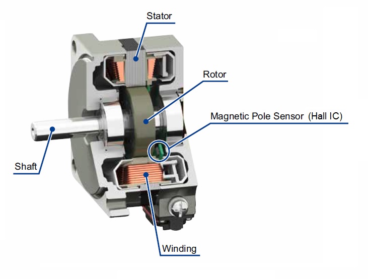
Figure 1
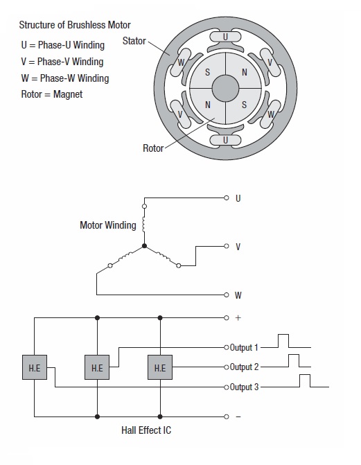
Figure 2
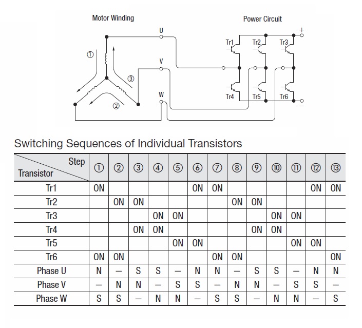
Figure 3
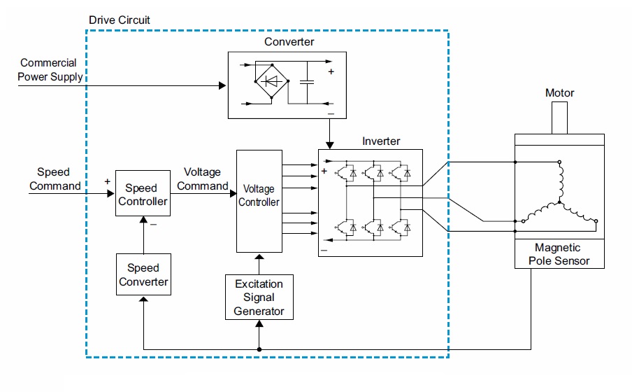
Figure 4
Speed-torque characteristics of brushless motors
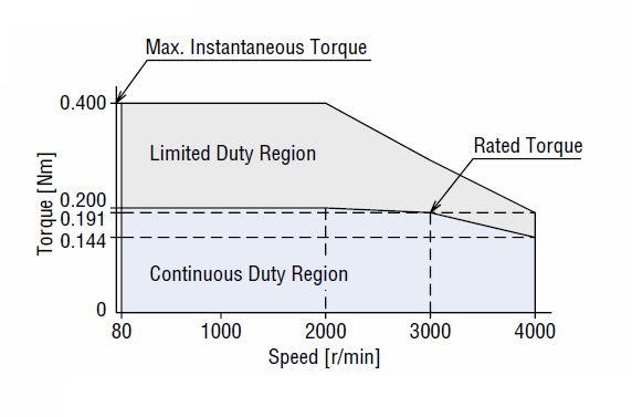
The diagram below shows an example of the characteristics of a brushless motor. Brushless motors have an almost constant rated torque from low to high speeds. The motors can be used without any loss of torque at low speeds, as is the case with AC speed control motors.
Limited duty region
This is an area of combined speed and torque that can be used for short periods of time. It is used to improve response during acceleration and deceleration.
Continuous duty region
This is an area of combined speed and torque that can be used in continuous operation.
Structure and lifetime of the electromagnetic brake of brushless DC motors
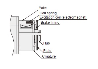
Motors with electromagnetic brake use a non-excitation-activated electromagnetic brake for position retention. An example of the construction is shown below.
When voltage is applied to the excitation coil, the armature is attracted to the electromagnet against the coil spring, the brake is released and the motor shaft is free to rotate.
When no voltage is applied, the armature is released and the coil spring causes the brake lining to press against the plate, locking the motor shaft in place.
Operation and lifetime
This brake can be used for holding the position when the motor is not excited. Do not use it for braking to stop a rotating load.
As the brake lining is not intended for braking, repeated braking will widen the gap due to wear, making normal operation impossible.
The lifetime for starting and stopping loads with a permissible load inertia moment is 5 million cycles.
Brushless DC motors in environments above 1000 m above sea level
At higher altitudes, the effectiveness of atmospheric heat dissipation is reduced, so it is necessary to take measures such as lowering the ambient temperature of the product. Below are the conditions for use at altitudes above 1000 m and below 2000 m above sea level.
Eligible products
- BMU Series*
- BLE2 Series*
- BLH Series
- BXII Series
* Except JV/JB/JH gears
Conditions for motors
If the motor is to be used above 1000 m above sea level and below 2000 m, lower the ambient temperature as shown in Figure 1.
For example, if a product with an upper ambient temperature limit of 40°C is used at 2000 m above sea level, the upper ambient temperature limit is 32°C.
For a reduction of the load torque refer to Fig. 2.
For example, when used at 2000 m above sea level, the upper limit of the load torque is 80% of the rated value.
Speed-torque characteristics of brushless motors
When calculating the torque values according to the above specifications, the torque values of the speed used are used.
The torque value at a given speed can be found in the speed-torque characteristic diagram as shown in Fig. 3.
Conditions for driver
If the motor is to be used above 1000 m above sea level and below 2000 m, lower the ambient temperature as shown in Figure 1.
For example, if a product with an upper ambient temperature limit of 40°C is used at 2000 m above sea level, the upper ambient temperature limit is 32°C.
When using geared motors
Please use it in a range less than 2000 m above sea level. If the altitude becomes high, then the temperature rise due to the difference between the outside air pressure and the heat dissipation will decrease the life of the oil seal and grease leakage inside the gearhead may occur. If grease leakage becomes a problem, periodically check for bleeding of the grease, attach the oil pan etc. to the equipment.

Figure 1

Figure 2
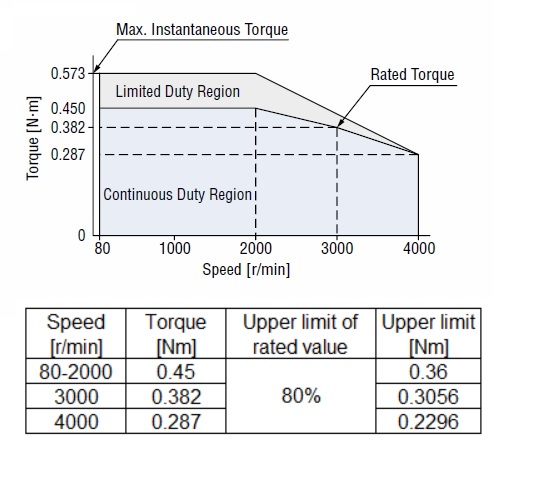
Figure 3: Exemplary calculation for a 120 W BMU motor at 2000 m above sea level.
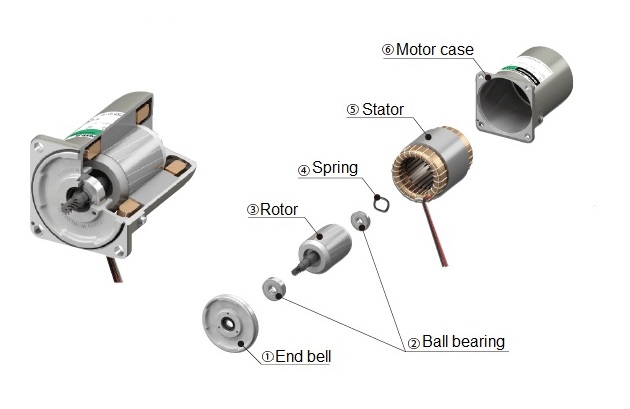
Structure of induction motors
1) End bell
Die-cast aluminium alloy product, machined. Press-fitted into the motor case.
2) Ball bearing
3) Rotor
Consists of laminated magnetic steel plates and die-cast aluminium alloy conductors.
4) Springs
5) Stator
Consists of a stator core made of laminated electromagnetic steel plates, polyester-coated copper wire windings and film for insulation.
6) Motor case
Die-cast aluminium alloy with machined interior.
Speed-torque characteristics of induction motors
The speed-torque characteristic of induction motors is shown in figure 1 below.
With no load, the motor rotates at a speed close to synchronous rotation speed, but as the load increases, the rotation speed decreases and the motor rotates at point P, where the load and the motor torque TP are in balance. If the load increases further and reaches point M, the motor cannot generate any more torque, so it reaches point R and stops. In other words, the range between R and M is unstable, and it is between M and O that the motor can operate stably.
Induction motors come in two types: capacitor start and run single-phase induction motors and three-phase induction motors, with single-phase types generally having less starting torque than operation torque. Three-phase types have relatively high starting torque characteristics (fig. 2).
The generated torque of a motor varies in proportion to almost the square of the power supply voltage. For example, if 110 V is applied to a motor with a rated voltage of 100 V, the generated torque will be approximately 120 %. At this point, the temperature rise of the motor may exceed the permissible temperature rise. If 90 V is applied, the torque will be approximately 80%. At this time, the motor may not operate as expected.
Therefore, use the power supply voltage within ±10% of the rated voltage, as large fluctuations in the power supply voltage may cause the motor temperature rise to exceed the permissible operating range or cause deterioration of torque, resulting in unstable operation.
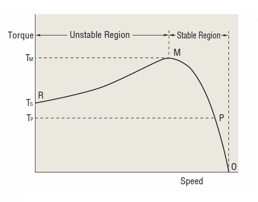
Figure 1
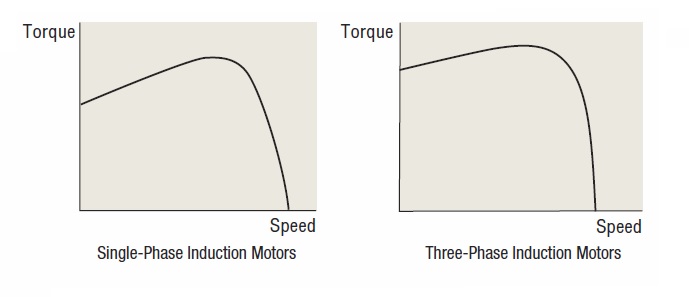
Figure 2
Temperature rise in induction motors
Temperature rise in motor
During motor operation, all losses inside the motor (copper losses, steel losses, etc.) become heat, which raises the temperature of the motor.
- For induction motors (continuous operation), the temperature rise saturates and the temperature drops to a constant temperature within 2-3 hours after the start of operation.
- For reversible motors (30 minutes rating), the temperature reaches the specified temperature within 30 minutes after the start of operation, and the temperature rises further if operation is continued.
Measurement method for temperature rise
Oriental Motor defines the temperature rise of a motor by the values measured using the following measurement method.
Thermometer method
A thermometer or thermocouple is fixed in the central part of the motor case and the temperature rise is measured when the motor is operated and the temperature rise is saturated, with the difference from the ambient temperature being the temperature rise.
Resistance change method
This measurement method measures winding temperature by the change in its resistance value. The winding resistance and ambient temperature of the motor wire before and after operation are measured with a resistance meter, thermometer or similar to determine the winding temperature rise value of the motor.
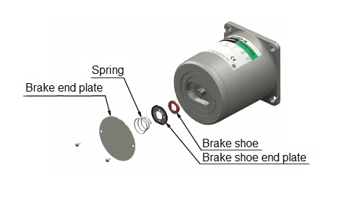
Structure of reversible motors
Reversible motors have a built-in friction brake mechanism (friction brake) at the rear of the motor. This brake mechanism is fitted for the following purposes:
- Frictional loads are applied to improve instantaneous reversibility characteristics
- Reduce overrun
Structurally, the brake shoes are subjected to constant pressure to friction. The brake shoes have an integral structure to minimise ageing and are made of materials with excellent friction resistance.
Although they have a certain degree of holding force, there is a limit to the braking force due to this structure, which we limit to approximately 10% of the motor's output power torque.
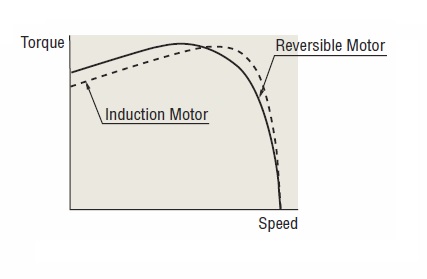
Speed-torque characteristics of reversible motors
Reversible motors are capacitor start and run single-phase induction motors, like induction motors, and their speed-torque characteristics are similar to those of the induction motors. However, reversible motors have a higher starting torque compared to induction motors in order to improve the instantaneous reversibility characteristics.
Operation time and temperature rise of reversible motors
Although reversible motors are '30 minutes rated', the operation time varies depending on the operation conditions, even in the case of short time intermittent duty operation. When a reversible motor is used in intermittent operation for short periods of time, a large current at motor start and reversing increases heat generation, but if the motor is stopped for a longer period of time, the natural cooling effect at motor standstill is greater and the motor temperature rise can be kept low.
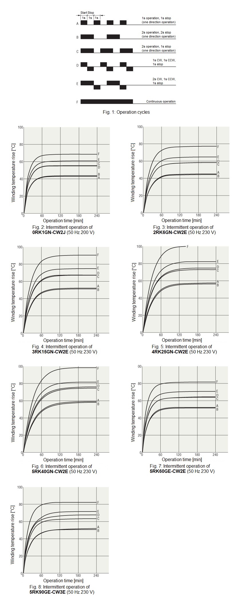
In case of intermittent operation
Conditions for intermittent operation are determined as shown in Fig. 1, A to E. F shows the conditions for continuous operation. Actual measurements of the temperature rise of our typical reversible motors under these conditions have been carried out.
Figures 2 to 8 show the results.
When measuring the temperature rise, the motor itself was suspended in the air, with almost no heat conduction, and under no load condition, which is the most severe for capacitor start and run motors in terms of temperature rise.
Note, however, that temperature rise may be higher due to the longer time required for starting and reversing, especially if the load is greater than the motor's rated torque or if there is a large inertia load.
Care should be taken to ensure that the temperature rise of the 4RK25GN-CW2E, for example, is kept below 80°C for winding temperature rise and below 90°C for motor case temperature during operation.
Figure 5: 4RK25GN-CW2E shows that continuous intermittent operation is possible if the operation and stop times are the same (conditions A and B). (Conditions C and D are the limit.) Also, the higher the output power of the motor, the shorter the time.
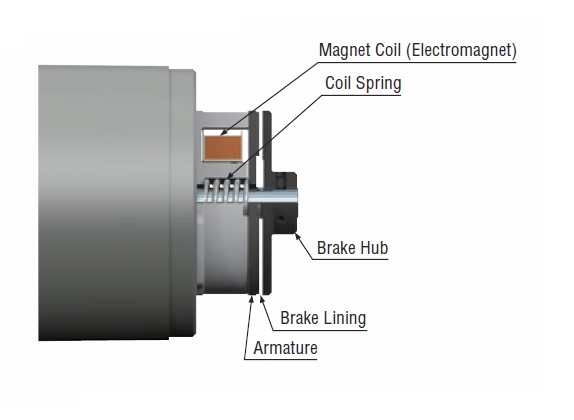
Structure and lifetime of the electromagnetic brake of AC motors
Electromagnetic brake motors use a power off activated type electromagnetic brake for braking. An example structure is shown below.
When voltage is applied to the excitation coil, the armature is attracted to the electromagnet against the coil spring, the brake is released and the motor shaft is free to rotate.
When no voltage is applied, the armature is released and the coil spring pushes the brake lining against the brake hub, fixing the motor shaft.
Operation and lifetime
The brake can be used for braking. The lifetime for repeated braking of permissible load inertia is 2 million cycles.
Overheat protection device for AC motors
If a motor in operation status is locked rotor condition due to an overload, or if the ambient temperature rises rapidly, or if the input increases for any cause, the temperature of the motor will rise rapidly. If left unattended, the insulation performance inside the motor will deteriorate, shortening its lifetime or, in extreme cases, even burning out the windings and causing a fire. To protect the motor against such thermal abnormalities, our UL Standards, CSA Standards, EN Standards or IEC Standards-compliant motors are equipped with the following overheat protective devices.
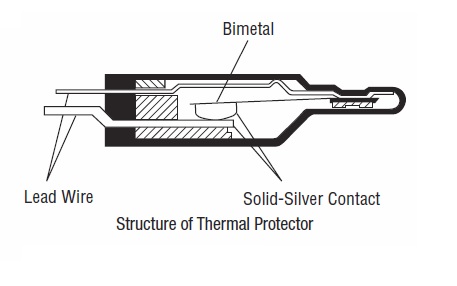
Thermal protector
Motors with frame sizes 70 mm, 80 mm, 90 mm and 104 mm have a built-in automatic return type thermal protector. The structure of the thermal protector is shown in the diagram below.
(The KIIS Series does not have a built-in overheat protective device (thermal protector), so use the electronic thermal function of the electromagnetic switch or inverter.)
The thermal protector is a bimetal system and uses pure silver contact points, which have the lowest electrical resistance of any metal and the second highest heat conduction after copper.
Operating temperature of the thermal protector
Open: 130±5°C (the operating temperature varies depending on the motor type)
Close: 85±5°C (the operating temperature varies depending on the motor type)
(The motor winding temperature when the thermal protector is operating is slightly higher than the above operating temperatures.)
Impedance protection
Motors with a frame size of 60 mm or less are equipped with impedance protection. Impedance-protected motors are designed to increase the impedance of the motor windings so that even if the motor is locked, the increase in motor current (input) is kept small and the temperature rise does not exceed a certain constant value.
Capacitor for AC motors
All our AC motors for single-phase power supplies are capacitor start and run motors. In capacitor start and run motors, the main winding and auxiliary winding are wound with polar axes that differ by 90° at an electrical angle. A capacitor is connected in series with this auxiliary winding and acts to advance the phase of the current in the auxiliary winding.
Motors employ vapour-deposited electrode capacitors recognized by UL. This type of capacitor uses a metal vapour-deposited plastic film as a component and is also commonly referred to as an SH (Self Healing) capacitor because of its self-healing action.
Capacitance
Incorrect capacitance of the capacitor can cause abnormality in vibration and heat generation in the motor, as well as loss of torque and unstable operation. Always use the capacitor included with the motor. Capacitance of capacitors is expressed in units of μF (microfarad).
Rated voltage
If the capacitor is used above the rated voltage, it may be damaged, resulting in smoking or ignition. Always use the capacitor included with the motor. The rated voltage of capacitors is expressed in units of volts (V). The rated voltage of the capacitor is displayed on the surface of the capacitor case. Note that this is different from the rated voltage of the motor itself.
Rated conduction time
Rated conduction time is the minimum design operating life of the capacitor when operating at rated load, rated voltage, rated temperature and rated frequency. 40,000 hours is the reference. If the capacitor is damaged at the end of its lifetime, smoking or ignition may result. It is recommended to replace the capacitor after the rated conduction time rating as a reference.
In the event of an abnormality in the capacitor, please consider a separate protective measure to ensure that the equipment is not affected.
Capacitors with safety mechanism
In the event of a dielectric breakdown in a capacitor, the capacitor can be safely disconnected from the circuit and a functional safety mechanism is provided to prevent smoking and ignition. Our products use UL recognised capacitors with safety mechanisms that satisfy the UL 810 failure current test of 10,000 A.
Torque motor features
- The torque varies as the applied voltage to the motor is changed.
- It has a large starting torque and sloping characteristics and can be used throughout the entire range of speed-torque characteristics.
- Unlike induction motors and reversible motors, the torque is stable at low speeds and when locked.
- When the load is constant speed, the rotation speed changes when the applied voltage is adjusted.
- If the applied voltage is constant, the rotation speed changes as the load changes.
Speed-torque characteristics of torque motors
For torque motors TM Series, adjustments to the torque setting voltage or torque potentiometer will change the applied voltage and thus the torque (Fig. 1).
Torque motors can also provide braking force when they are turned in the opposite direction, e.g. by an external force, relative to the motor rotation direction. These brake characteristics are called reverse-phase brakes. The area expressed by the normal speed-torque characteristics is called the duty region, while the area that acts as a reverse-phase brake is called the braking region (Fig. 2).
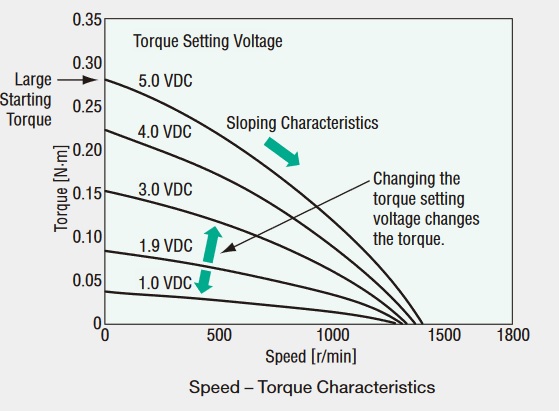
Figure 1
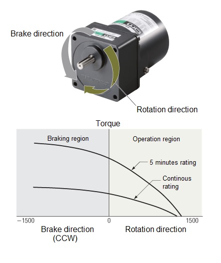
Figure 2
AC motors in environments above 1000 m above sea level
At higher altitudes, the effectiveness of atmospheric heat dissipation is reduced, so it is necessary to take measures such as lowering the ambient temperature of the product. Below are the conditions for use at altitudes above 1000 m and below 2000 m above sea level.
Eligible products
- World K Series
- KIIS Series
- KII Series
- BH Series
(Except when combined with right-angle gearheads.)
Operating conditions when the power supply voltage is single-phase
If the motor is to be used above 1000 m above sea level and below 2000 m, lower the ambient temperature as shown in Figure 1.
For example, if a product with an upper ambient temperature limit of 40°C is used at 2000 m above sea level, the upper ambient temperature limit is 32°C.
Operating conditions when the power supply voltage is three-phase
If the motor is to be used above 1000 m above sea level and below 2000 m, lower the operating ambient temperature or reduce the load torque as follows.
For a reduction of the ambient temperature refer to Fig. 1.
For example, if a product with an upper ambient temperature limit of 40°C is used at 2000 m above sea level, the upper ambient temperature limit is 32°C.
For a reduction of the load torque refer to Fig. 2.
For example, when used at 2000 m above sea level, the upper limit of the load torque is 80% of the rated value.
When using geared motors
Please use it in a range less than 2000 m above sea level. If the altitude becomes high, then the temperature rise due to the difference between the outside air pressure and the heat dissipation will decrease the life of the oil seal and grease leakage inside the gearhead may occur. If grease leakage becomes a problem, periodically check for bleeding of the grease, attach the oil pan etc. to the equipment.
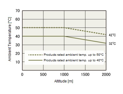
Figure 1
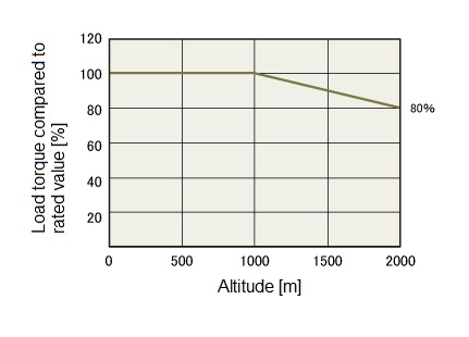
Figure 2