Transportable mass, thrust force and pushing force of linear & rotary actuators
Transportable mass
The transportable mass is the load mass that can be moved according to the specifications of the linear & rotary actuator (Fig. 1).
One value is given for the horizontal and one for the vertical direction. The values can be found in the specifications.
The load mass affects the relationship between the positioning distance, positioning time and acceleration in transportation.
When selecting a linear & rotary actuator, it is necessary not only to confirm the transportable mass, but also to check that it satisfies the positioning distance and other operation conditions.
For information on the relationship between load mass, positioning distance, positioning time, positioning operation speed and acceleration in transportation, please refer to the appropriate sections.
Thrust force (Fig. 2)
Thrust is the propulsive force with which an electric actuator can propel a load. It is the force acting on a moving load.
Upper limit values are listed in the specifications.
Upper limit of thrust force
The upper limit of the thrust force is determined by the estimated lifetime of the driven components (ball screws, guides, bearings, etc.; Fig. 3).
The estimated lifetime is calculated on the basis of dynamic loads.
The products have thrust force limits set to ensure stable transportation from low speeds to high speeds (Fig. 4).
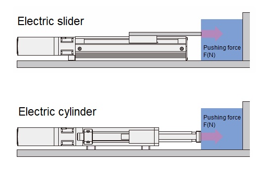
Pushing force
The pushing force is the applied pressure when the linear & rotary actuator is pushed against a load (Fig. 5). It is the force exerted against a load that is standing still.
The values are given in the specifications.
Upper limit of pushing force
The upper limit of the pushing force is determined by the static load (basic static rated load) applied to the components supporting the load (ball screws, guides, bearings, etc.; Fig. 6).
Stepper motors in linear & rotary actuators provide particularly high torque at lower speeds (Fig. 7).
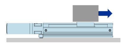
Figure 1: Transportable mass
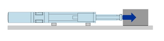
Figure 2: Thrust force
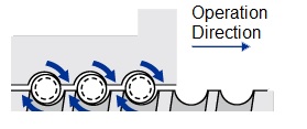
Figure 3: Upper limit of thrust force
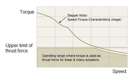
Figure 4
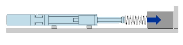
Figure 5: Pushing force
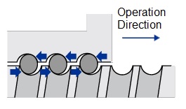
Figure 6: Upper limit of pushing force
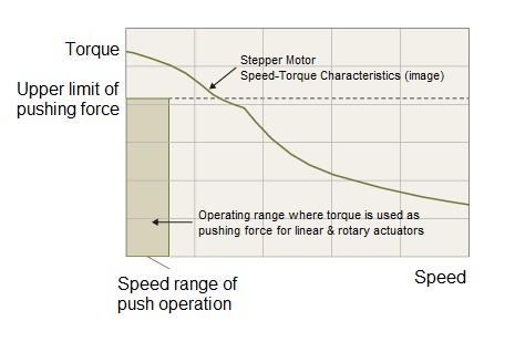
Figure 7
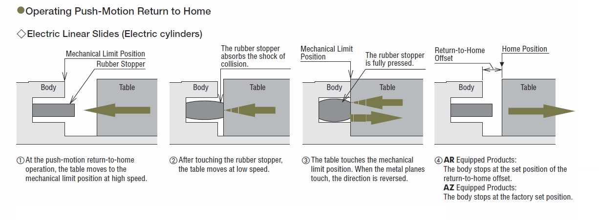
Push-Motion return-to-home operation of electric slides and cylinders
Push-motion return-to-home operation is performed by pushing the table against the body of the mechanical part. High-speed return-to-home operation is possible thanks to the development of a special rubber stopper and a structure that presses the table against the end face of the metal part.
Applicable products:
EAS Series
EZS Series/EZS Series cleanroom type
EAC Series
(Push-motion return-to-home operation is not possible with actuators equipped with AR Series pulse-input type)
Note:
- When using push-motion return-to-home operation, check the dynamic permissible moment value.
- When using push-motion return-to-home operation, make sure that the home offset amount is set and the push-motion return-to-home operation current value is set and confirmed.
Push-Motion operation of electric slides and cylinders
Push-motion operation is continuous pressure operation against the load.
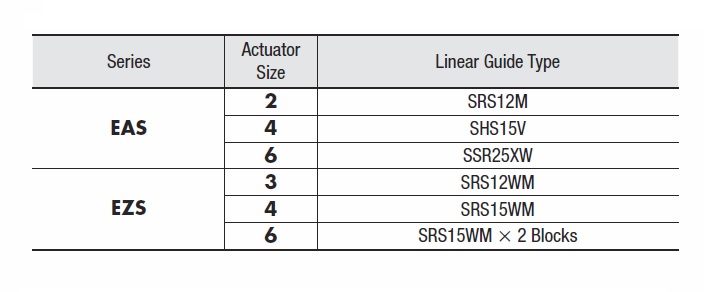
Linear guide types of electric linear slides
The linear guides used in electric linear slides are manufactured by THK CO., LTD.
The models used for each series are shown in the table below.
Maintenance of electric sliders and cylinders
Long-term maintenance-free components are used for the ball screw and guide rail (electric sliders only).
The ball screws are fitted with a lubrication system QZ* and the linear guides with ball retainers, which significantly extends the grease maintenance cycle.
We have confirmed that our electric sliders and cylinders have no problems with the ball screw and linear guide without maintenance until the expected lifetime.
However, grease deterioration depends on operating conditions and the operating environment. In actual use, grease should be maintained in accordance with the table shown in Fig. 1.
* The clean room version is not equipped with the QZ lubrication system.
(“Ball retainer" is a registered trademark of THK Co.)
The grease used for maintenance of each product is shown in Fig. 2.
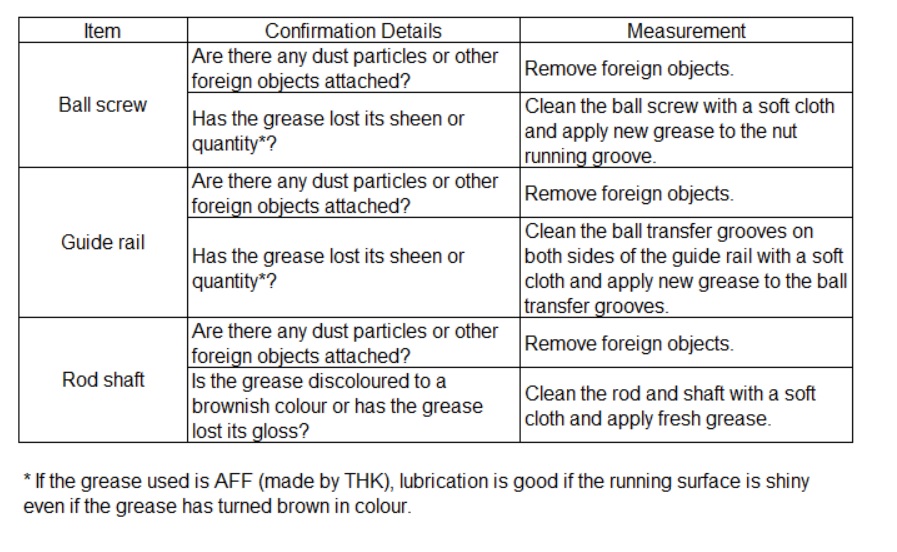
Figure 1
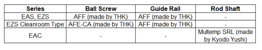
Figure 2
Specifications of a motor with rack-and-pinion system (L Series)
Three of the most important specifications of a motor with rack-and-pinion system are as follows:
- Rack speed
- Max. transportable mass
- Holding force
Rack speed
The rack speed can be calculated by the pulse speed from the controller using the formula shown in Fig. 1.
Max. transportable mass
Please refer to the specifications in the product catalogue.
The maximum transportable mass in the specification table is the value when the rack is moved horizontally. When the rack is moved vertically, the value in the specifications is obtained by subtracting the rack mass (please refer to the dimensions in the catalogue) or the force equivalent to the rack mass (rack mass x 9.807) from the value in the specifications.
Holding force
Please refer to the product specifications.
Rack backlash (default value)
The rack is supported by rack bushes in two locations on the rack case. A slight clearance is provided between the rack bushings and the rack in order to allow the rack to move in the direction shown in Fig. 2.
A, B direction: 2 mm or less
C direction (backlash): 0.5 mm or less
D direction: 0.5° or less
- Backlash in directions A and B are measured at 500 mm from the case end face.
- Backlash increases as the rack is used. If the rack is used in applications where backlash is a problem, provide an external guide.
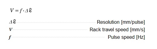
Figure 1: Formula for calculating the rack speed
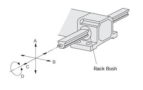
Figure 2: Rack backlash directions
Repetitive positioning accuracy of linear actuators
Please note the following points to ensure the repetitive positioning accuracy of the specifications.
1) Ensuring rigidity of peripheral parts
The rigidity of the linear guide and other mechanical parts used must be commensurate with the load mass and external force. If the rigidity is insufficient, the specifications may not be met due to deflection or other reasons.
Use mounting fittings for installing the actuator and fittings for connecting the actuator to the workpiece that have rigidity commensurate with the load mass and external force. If the rigidity is insufficient, the specifications may not be met due to deflection, etc.
2) Sensors
Use a high-precision origin sensor (e.g. photo-micro sensor). Repetitive positioning accuracy does not include home search accuracy.
3) Actuator temperature rise
The actuator may generate significant heat depending on the driving conditions. This causes the built-in ball screw to elongate, resulting in position displacement as shown in Fig. 1 (reference values). To minimise the effect of temperature on repetitive positioning accuracy, adjust the input current value to the actuator and design the peripheral parts in consideration of heat dissipation.
Reference:
Adjusting the input current of the actuator changes the temperature rise value of the actuator. This is effective when there is a margin in the starting characteristics and holding force.
In addition to this, a review of the operating duty also affects the temperature rise value (Fig. 2 shows an operating duty of 75%).
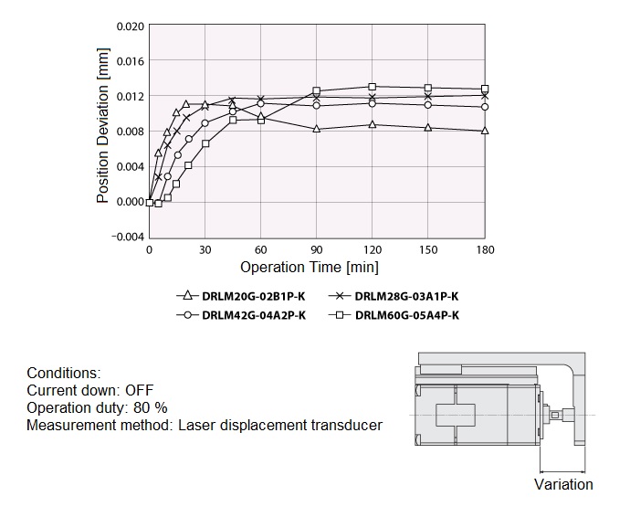
Figure 1: Position deviation in relation to operation time
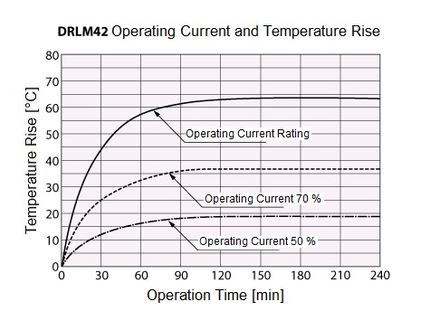
Figure 2: Operating current and temperature rise
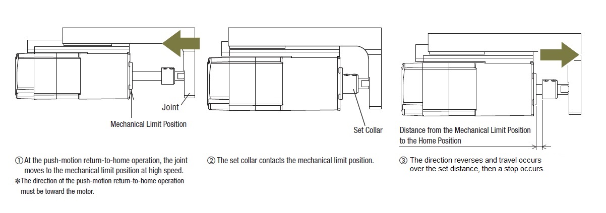
Push-Motion return-to-home operation of linear actuators
Push-Motion return-to- homing operation is a homing method based on the mechanical limit position and the position where the set collar is pushed against.
It can only be used when the set collar advances towards the motor.
Eligible products:
- DR Series
- DRS2 Series
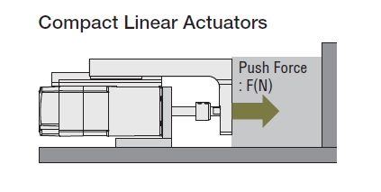
Push-Motion operation of linear actuators
The push-motion operation applies pressure continuously when the moving parts contact the load.
Maintenance of linear actuators
Maintenance cycles
If the actuator is operated for 8 hours a day, maintenance should be carried out every period in the table shown in Fig. 1.
For continuous day/night operation or high operating rates, shorten the maintenance cycle according to the situation.
External check
Please confirm the items shown in the overview in Fig. 2.
External cleaning
- Clean the external surface of the actuator as required.
- Wipe off any dirt with a soft cloth.
- Do not blow compressed air. Dust may enter through the gaps.
- Do not use petroleum solvents as they may damage painted surfaces.
- If the surface is heavily soiled, wipe with a soft cloth dampened with neutral detergent.
Internal check
Visually check the internal condition of the actuator. Check the items shown in Fig. 3.
Lubrication is good if the running surface is shiny, even if the grease is discoloured.
Grease replenishment
If the grease on the threaded shaft or linear guide becomes dirty, wipe it off thoroughly with a rag and then apply new grease. The grease should be checked after one week after initial operation and once a month thereafter.
The grease used for maintenance of each product is shown in Fig. 4.
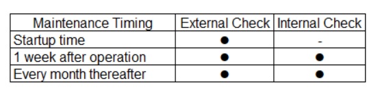
Figure 1: Maintenance cycles
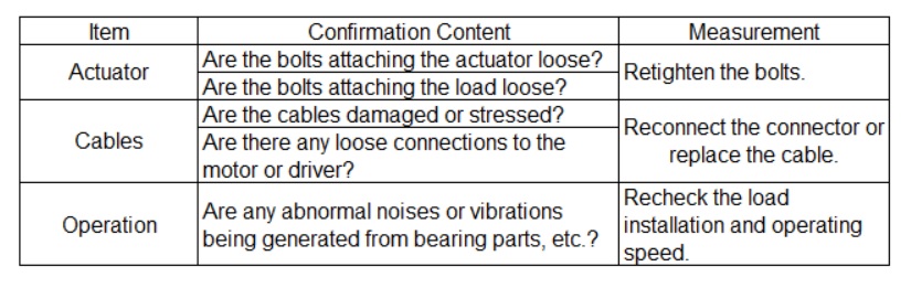
Figure 2: External check
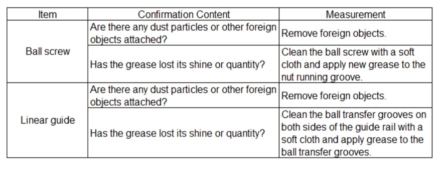
Figure 3: Internal check
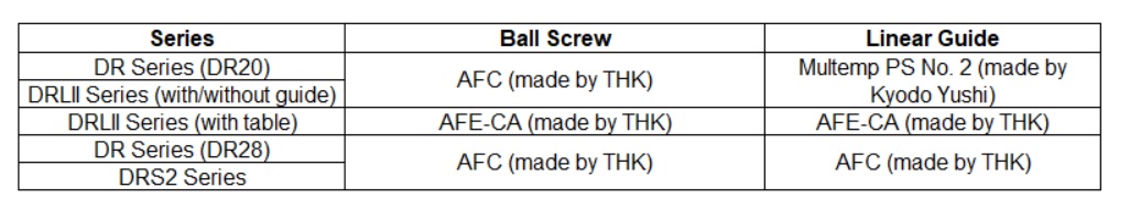
Figure 4: Grease types
Actuators in environments above 1000 m above sea level
At higher altitudes, the effectiveness of atmospheric heat dissipation is reduced, so it is necessary to take measures such as lowering the ambient temperature of the product.
Applicable products:
Products equipped with AZ-motor
Electric linear slides: EAS Series, EZS Series
Electric cylinders: EAC Series
Rotary actuators: DGII Series
Linear actuators: DR Series, DRS2 Series
Rack-and-pinion-systems: L Series
Products equipped with AR-motor
Electric linear slides: EAS Series, EZS Series
Electric cylinders: EAC Series
Rotary actuators: DGII Series
For the detailed conditions please refer to the same topic in the section about stepper motors.
Role of gearheads
The role of deceleration is closely related to the development of motors. Initially, when AC motors only rotated, deceleration gears were mainly used as speed changers to change the motor's rotation speed and as amplification of torque. However, when motors were given variable speed functions, their purpose became less as a speed changer and more as an amplification of torque.
Furthermore, as position and speed control became required, stepper and servo motors became more widespread, and gearheads were used to increase inertia force as well as amplification of torque, and to reduce vibration in stepper motors. In addition, the high positioning accuracy of motors led to a demand for backlash-free gears that differed from those used in AC motors.
In view of the above, Oriental Motor's gearheads have been developed with appropriate characteristics in each case so as not to impair the characteristics of the motor in which they are assembled, and as AC motor gearheads are used as main drive with long operation cycles they are designed with high permissible torque, long life, low noise and a full range of gear ratios in mind. On the other hand, gearheads for stepper motors and servo motors are designed for high-precision positioning accuracy applications, with high accuracy, high permissible torque and high-speed rotation (for servo motors) as important factors.
Gearhead specifications
Torque amplification
The torque at the gearhead output shaft can be calculated using the formula shown in Fig. 1.
Permissible torque
As the gear ratio increases, the output power increases proportionally, but the load torque that can be transmitted by the gearhead may be limited by the gear material and other conditions. The maximum permissible torque limiting value is called the maximum permissible torque (Fig. 2).
The permissible torque is the torque that can be driven by the gearhead output shaft corresponding to the combined motor, and transmission efficiency at normal ambient temperature is also taken into account, and the values are shown for each gear ratio.
Transmission efficiency (Fig. 3)
Transmission efficiency is a value determined by the structure and gear ratio of the gear, such as the product line and the number of gear stages. In addition, transmission efficiency varies with ambient temperature. Note that when operating in a low-temperature environment, the transmission efficiency may deteriorate and output torque may decrease.
Speed and rotation direction
Speed
The speed of the gearhead output shaft can be calculated using the formula shown in Fig. 4.
The speeds shown for combinations with AC motors are calculated values based on the synchronous speed of the motor, so the actual speed will be a number of rotations per cent lower depending on the size of the inductive load. For some models, the actual gear ratio and nominal gear ratio may differ slightly.
Rotation direction
The rotation direction indicates the direction of rotation when viewed from the output shaft (Fig. 5). The motor rotation direction and the rotation direction of the gearhead depend on the gear ratio of the gearhead.
Permissible radial load and permissible axial load (Fig. 6)
Permissible radial load
The permissible radial load indicates the permissible value of the load that can be applied at right angles to the gear output shaft. The permissible value is indicated by the position where the load is applied.
Permissible axial load
The permissible axial load indicates the permissible value of the load that can be applied to the gear output shaft in the axial direction.
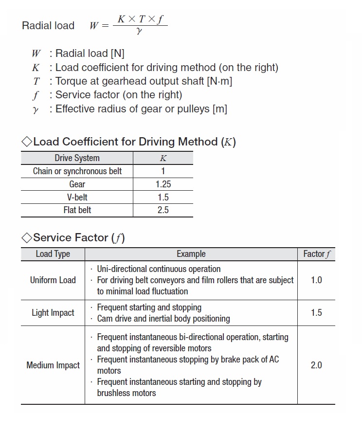
Formula for radial load
When chains, gears or belts are used as transfer mechanisms from the gearhead output shaft, a radial load is always applied to the output power shaft. For details please refer to the section about the formula for radial load.
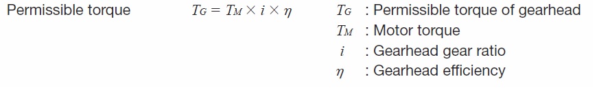
Figure 1: Formula for calculating the permissible torque of gearheads
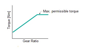
Figure 2: Max. permissible torque
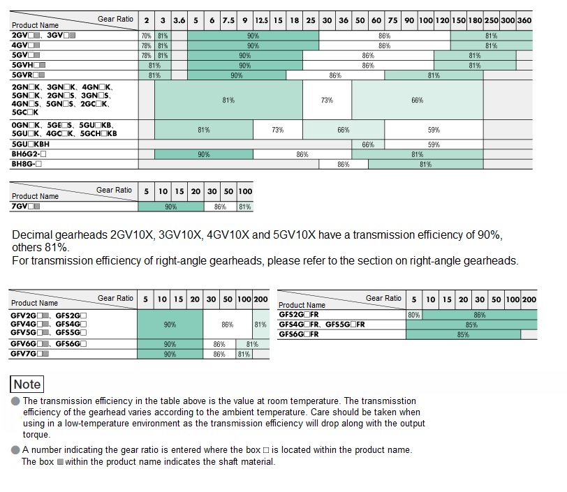
Figure 3: Gearhead transmission efficiency
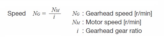
Figure 4: Formula for calculating the speed
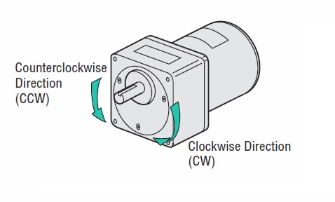
Figure 5: Rotation directions
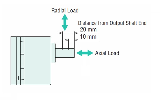
Figure 6: Permissible axial and radial load
Formula for calculating the radial load
The radial load can be calculated using the formula shown below.
Permissible inertia moment
If the moment of inertia linked to the gearhead is large, a large momentary torque is generated during frequent intermittent operation starts (or stops with electromagnetic brakes and brake packs). This excessive shock load can lead to damage to the gearhead and motor.
The permissible moment of inertia at the gearhead output shaft is shown according to the combined motor characteristics. In cases where frequent intermittent operation causes shock loads, the number of start/stop cycles should be set as a reference of 2 million cycles, even if the load is within the permissible load inertia moment.
If permissible moment of inertia values are blank for combination motors, e.g. GN gear or BH Series, the formula shown in Fig. 1 can be used to calculate the permissible moment of inertia.
The formula of Fig. 1 implies that at reduction ratios of 60 and above, the moment of inertia is limited by the design strength of the components, but in general, deceleration at the gearhead increases the moment of inertia on the gear output shaft by a factor of the square of the reduction ratio of the moment of inertia at the motor shaft. In other words, deceleration allows a larger moment of inertia to be driven.
Permissible inertia moments at the motor shaft are shown in Fig. 2.
Note:
In combination with AC motors, do not perform instantaneous bidirectional operation. The high starting torque of the motor may cause premature damage.
When changing the rotation direction, stop the motor once and reverse it.
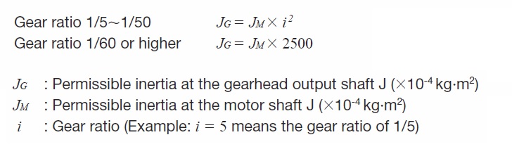
Figure 1: Calculation of permissible inertia moment
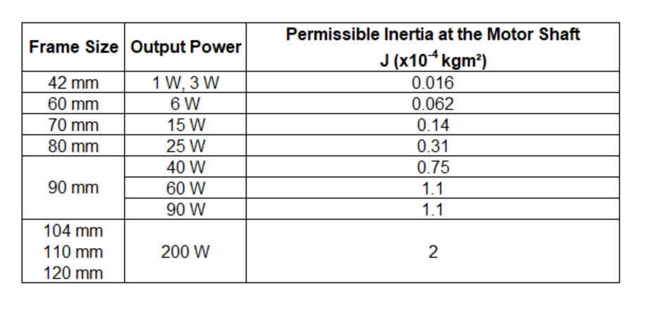
Figure 2: Permissible inertia moments at the motor shaft of AC motors
Structure of gearheads
Fig. 1 shows a structural drawing of a gearhead with the output shaft arranged parallel to the motor shaft. The names and roles of the various parts are as follows.
Backlash
Backlash is the gap between tooth surfaces when engaged, as shown in the diagram below. The gap between the gears is set to absorb errors in the assembly of the gearheads, for example.
Backlash has no effect in unidirectional operation, but when the rotation direction is changed and positioning operation is carried out, a deviation from the theoretical rotation angle is caused by the magnitude of the backlash. Therefore, we remove or adjust the backlash on gearheads for stepper motors and servo motors that are capable of high positioning accuracy, so that high positioning accuracy operation can be achieved.
The backlash values for each gearhead are the initial values at no load.
Sealing insert (Fig. 3)
Grease lubrication is used for the lubrication of the gears in our gearheads.
Depending on the degree of grease sealed in and the degree of protection when combined with the motor, an oil seal, O-ring or gasket is used in the sealing structure.
The sealing capacity of the oil seal sealing the sliding portion of the shaft varies greatly depending on the operating ambient temperature and operating conditions, but a reference period of 10,000 hours should be used.
Even if a small amount of grease oozes out on rare occasions, it is not necessary to inject grease, as the seal is filled with an appropriate amount of grease to prevent premature damage.
In order to improve the sealing capacity of the oil seal, special oil seals are being used from some gearheads.
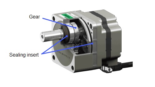
Figure 1: Gearhead structure
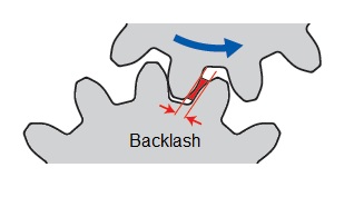
Figure 2: Backlash
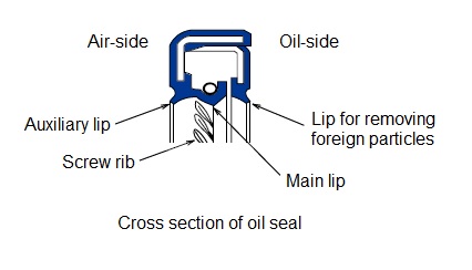
Figure 3: Oil seal
Gearheads for AC Motors
As gearheads are designed with high permissible torque, long life, low noise and a full line-up of gear ratios as important features.
Right-Angle gearheads
Right-angle gearheads are user-friendly products that enable effective installation in limited space and reduce the number of couplings and other power transmission components (hollow shaft gearheads). Our right-angle gearheads include right-angle, hollow shaft gearheads using hypoid gears, right-angle, hollow shaft gearheads and solid shaft gearheads, and right-angle, solid shaft gearheads using worm gears or screw gears.
Right-angle gearheads with face gears (disc-shaped gears) and spur gears are also available for high positioning accuracy.
Hypoid gears
Hypoid gears are conical gears that transmit power between skew gear shafts and have a curved tooth trace. They offer high strength due to the arrangement of hypoid in the first stage and larger gears in the last stage.
Worm gears
These gears have a history as old as that of spur gears, but due to their difficulty in machining and low efficiency, they were used in limited applications compared to spur gears. However, we have taken advantage of the fact that the axis can be set at right angles and that they can be used for high deceleration ratios, and have further increased the efficiency of these gears compared to normal worm gears by increasing the angle of rotation.
Crossed helical gears
Crossed helical gears are ordinary helical gears on their own. However, parallel shaft helical gears have equal torsion angles to each other and are in contact with gears with opposite torsion directions, whereas crossed helical gears are designed with torsion angles so that the shafts are at right angles to each other. Due to their point contact, crossed helical gears are often used with relatively light loads and are mainly used with low deceleration ratios in our right-angle shaft gearheads.
Parallel shaft gearheads
Our parallel shaft gearheads use spur gears and helical gears. Helical gears are used in particular for their noise reduction and high strength.
GV/GFV gearheads
The GV and GFV gearheads feature improved gear case rigidity, further improvements in gear machining technology and higher accuracy in assembly technology, resulting in lower noise.
The use of carburised and hardened gears with high strength and larger diameter bearings have achieved permissible torque two to three times higher than that of conventional GN-K gearheads and a rated life of 10,000 hours.
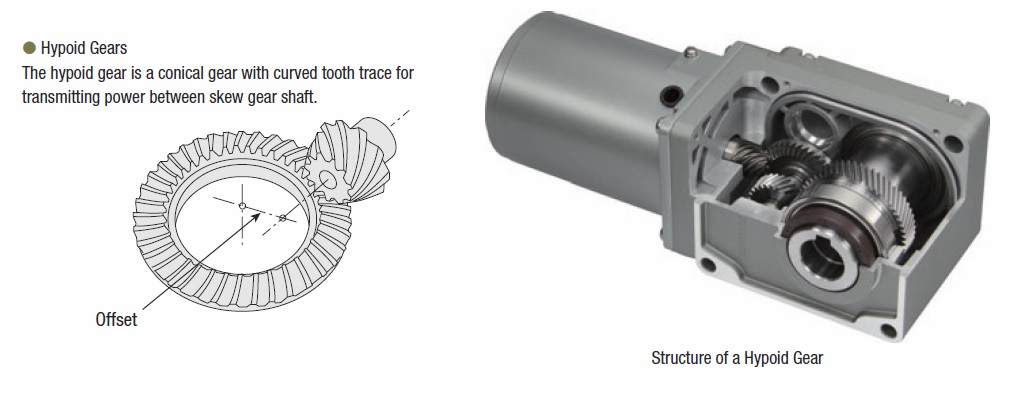
Figure 1: Hypoid gears
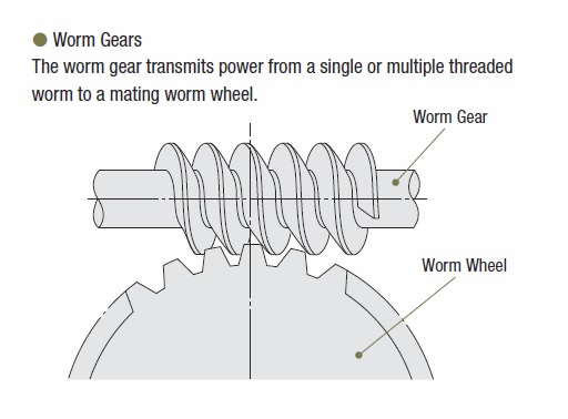
Figure 2: Worm gears
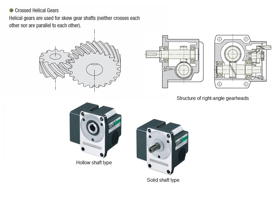
Figure 3: Crossed helical gears
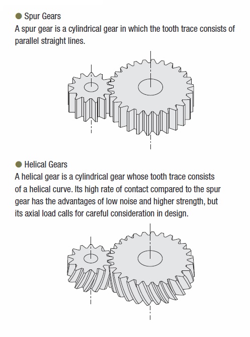
Figure 4: Parallel shaft gearheads
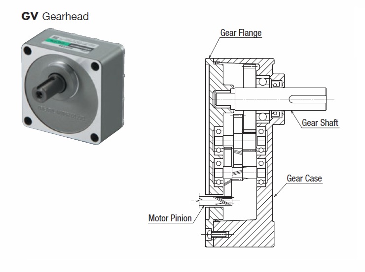
Figure 5: GV/GFV gearheads
Gearheads for brushless motors
Parallel shaft gearheads
GFV gearheads
Please refer to „Gearheads for AC Motors“.
CS gearheads
Please refer to “Gearheads for stepper motors”
Right-angle hypoid gears
Please refer to „Gearheads for AC Motors“.
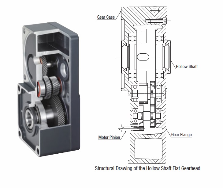
Hollow shaft flat gearheads
Hollow shaft flat gearheads are designed so that permissible torque is not saturated even at high gear ratios. This product is also suitable for applications requiring high permissible torque. They can also be installed effectively where space is limited and reduce the number of couplings and other power transmission components.
Furthermore, the combination with a flat brushless motor enables compact installation without the need for a right-angle shaft mechanism.
The structure of the hollow shaft flat gearhead extends the space volume by extending the arrangement of the gear shaft in the longitudinal direction, compared with conventional parallel shaft gearheads, thereby improving gear case rigidity and increasing the diameter of the gears and bearings at the same time.
This has enabled the output shaft to be hollowed without changing the parallel shaft structure, resulting in higher permissible torque and longer life of the product.
The parallel shaft structure also has the advantage that the transmission efficiency of the gear is higher than with a right-angle shaft mechanism.
Gearheads for stepper motors and servo motors
Gearheads for stepper motors and servo motors are designed for high-precision positioning accuracy applications, with high accuracy, high permissible torque and high-speed rotation (for servo motors) being of note.
In addition, mechanisms have been developed to reduce backlash and guarantee backlash in combination with the motor. In general, compared to AC motors with the same frame size, stepper motors have a higher output power torque and servo motors rotate at higher speeds, so that high torque and high speeds are supported so that these motor characteristics are not compromised.
CS gearhead (Fig. 1)
The CS gear is a parallel shaft gear reduction mechanism and is a product with the output shaft arranged in the centre of the frame size.
A salient on one side of the gear case provides space for the arrangement of the gears, enabling flexible installation of the centre shaft. In addition, the optimised design using the salient has achieved a larger diameter for the gears and bearings. This has increased the permissible torque, permissible radial load and permissible axial load of the product.
TS gearhead (Fig. 2)
TS gears have reduced the effect of backlash by improving the finishing accuracy of the gear machining and by implementing gear machining that takes into account the dimensional variation caused by heat treatment. In addition, the output shaft gears undergo high-precision finishing after heat treatment to eliminate the effects of dimensional changes caused by heat treatment.
As a result, the TS gear has a simple structure that requires no special adjustment mechanism.
TH gearhead (Fig. 3)
TH gears use tapered gears for the output power stage of the spur gear deceleration gear and the gears that contact it. Tapered gears have continuously varying dislocations in the axial direction. Fine adjustment between these tapered gears suppresses backlash.
FC gearhead (Fig. 4)
FC gears are right-angle shaft type gears consisting of a face gear (disc-shaped gear) and spur gear. Our unique high accuracy finishing accuracy has succeeded in reducing the size and high strength of the face gear, resulting in a compact right-angle shaft with reduced backlash.
PS gearhead (Fig. 5)
PS gears consist of gears of a planetary gear system. It consists of three basic components: sun gear, planetary gear and internal gear. There are several planetary gears outside the central shaft-mounted sun gear (in the single-stage type this is the motor shaft). The planetary gears are located outside of the sun gear and orbit around the central axis via the internal gears. The orbit of the planetary gears results in rotation of the output shaft via the carrier.
High permissible torque
In conventional spur gear mechanisms, the gear contact is one-to-one, so the strength of a single gear determines the torque that can be transferred. However, in a planetary gear mechanism, torque is distributed and transmitted across several planetary gears, so a large amount of torque can be transmitted.
The torque applied to a single gear in a planetary gear mechanism is shown in Fig. 6.
PN gearhead (Fig. 7)
The PN gear is a gear of the same planetary gear mechanism as the PS gear. In addition to improving the finishing accuracy of each component, a backlash eliminator mechanism has been adopted to achieve a backlash within 0.05° of the specification value. The backlash eliminator mechanism consists of an upper and lower arrangement of internal gears and planetary gears, with the internal gears twisted in a circumferential direction. The upper level internal and planetary gears eliminate backlash in the CW direction, while the lower level internal and planetary gears eliminate backlash in the CCW direction. The scissors gear system is applied to achieve non-backlash from low gear ratios.
High permissible torque
PN gears use the same planetary gear mechanism as PS gears, which allows transmission torque to be distributed over several gears, resulting in high permissible torque. For details, see the 'High permissible torque' section for PS gears.
Angular transmission accuracy (Fig. 8)
This is the error between the theoretical rotation angle of the output shaft calculated from the number of input pulses output and the actual rotation angle. It is expressed as the width between the minimum and maximum values of the error when a single rotation of the output shaft is measured from an arbitrary position.
HPG gearhead (Fig. 9)
This planetary gear deceleration equipment applies thin-walled elastic gear technology to the internal gears of planetary gears. This utilises the elastic deformation of the internal gear to achieve low backlash without any adjustment mechanism.
Planetary gear deceleration has a structure in which the sun gear and planetary gear, and the planetary gear and internal gear mesh with each other simultaneously. Therefore, if the backlash is reduced only by the dimensional accuracy of the components, dimensional errors can cause interference between the meshing parts, resulting in uneven rotational torque and noise.
In order to solve these problems, thin-walled elastic internal gears were developed, which have the function of reducing interference between the meshing parts and sufficient strength, resulting in the Harmonic Planetary Gear®, a planetary gear deceleration system with a revolutionary structure. Harmonic Planetary® has almost no backlash variation within the lifetime of the gear.
(Copyright © 1999 HARMONIC DRIVE SYSTEMS INC. All Rights Reserved.)
Harmonic Planetary® is a registered trademark of Harmonic Drive Systems Inc.
Angular transmission accuracy (Fig. 10)
This is the error between the theoretical rotation angle of the output shaft calculated from the number of input pulses output and the actual rotation angle. It is expressed as the width between the minimum and maximum values of the error when a single rotation of the output shaft is measured from an arbitrary position.
Harmonic gearhead (Fig. 11 and 12)
The harmonic gear, which offers unparalleled high positioning accuracy for a deceleration gear, consists of three basic components: Wave Generator, Flexspline (deformable cylindrical steel bush) and Circular Spline (rigid cylindrical outer ring).
Wave Generator
A thin-walled ball bearing is fitted around the periphery of an oval cam, giving the whole component an oval shape. The inner wheel of the bearing is fixed to the oval cam, while the outer ring is elastically deformed via the ball. It is mounted on the motor shaft.
Flex spline
The flex spline is a metal-elastic component with a thin-walled, cup-shaped body. The outer circumference of the cup opening is engraved with teeth. The gear output shaft is attached to the bottom of the flex spline.
Circular spline
The circular spline is a rigid internal gear. The inner circumference is engraved with teeth of the same size as the flex spline and has two more teeth than the flex spline. The outer circumference is fixed to the gear case.
Accuracy
Harmonic gears, unlike deceleration gears with spur gears, have no backlash (tooth contact play). The large number of teeth that mesh simultaneously averages out the effects of tooth pitch errors and accumulated pitch errors on rotation accuracy, resulting in high positioning accuracy. In addition, due to the high deceleration ratio of harmonic gears, the torsional rigidity of the motor output shaft when load torque is applied to it is much smaller than that of the motor alone or other geared motors. The high rigidity makes them resistant to load fluctuations and enables stable positioning. If high positioning accuracy or rigidity is requested, refer to the characteristics shown in Fig. 13.
Angular transmission accuracy (Fig. 13)
This is the error between the theoretical rotation angle of the output shaft calculated from the number of input pulses output and the actual rotation angle. It is expressed as the width between the minimum and maximum values of the error when a single rotation of the output shaft is measured from an arbitrary position.
The values of Fig. 13 are values under no load conditions (reference value for the gear section). In actual applications, however, a frictional load is always generated, resulting in displacement corresponding to the frictional load. If the frictional load is constant, the displacement is constant in unidirectional operation, but when operating in both back-and-forth operation, the displacement is twice as large in back-and-forth operation. The displacement can be estimated from the following torque - torsion characteristics shown in Fig. 14.
Torque - torsion characteristics (Fig. 14)
The torque - torsion characteristics in the graph are measurements of displacement (torsion) when the motor shaft is fixed and a load (torque) is gradually applied to or reduced from the forward or reverse direction on the output shaft. When a load is applied to the output shaft in this way, displacement occurs due to the spring constant of the gear.
This displacement occurs when an external force is applied at a stop or when the drive is subjected to a frictional load. Depending on the magnitude of the load torque, this slope can be approximated by spring constants in the three categories shown in Fig. 15, which can be estimated by calculation.
The torsion angle determined by the calculation is for the harmonic gear alone (Fig. 16).
Hysteresis loss
As can be seen in the torque - torsion characteristics (Fig. 14), even after applying torque up to the permissible torque in the forward and reverse direction and then reducing the torque to zero, the torsion angle is not completely zero and a small amount of torsion remains (B-B' in Fig. 14).
This is called hysteresis loss and this hysteresis loss is designed to be within 0.034°.
When external forces are applied when stopping, when acceleration/deceleration torque is applied in inertia load, or when frictional load is applied during drive, a slight torsion may remain due to this hysteresis loss even after the load is zeroed.
Lost Motion (Fig. 17)
As harmonic gears have no backlash, a reference to the accuracy of the gear is expressed as lost motion.
Lost motion is the total displacement that occurs when a torque of approximately 5% of the permissible torque is applied to the gear output shaft.
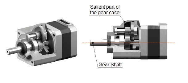
Figure 1: CS gearhead
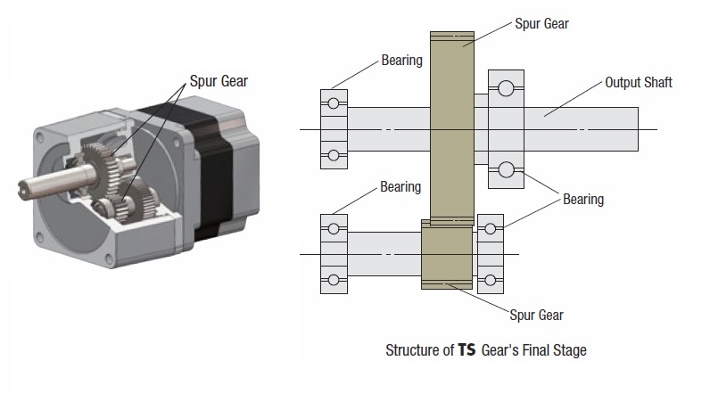
Figure 2: TS gearhead
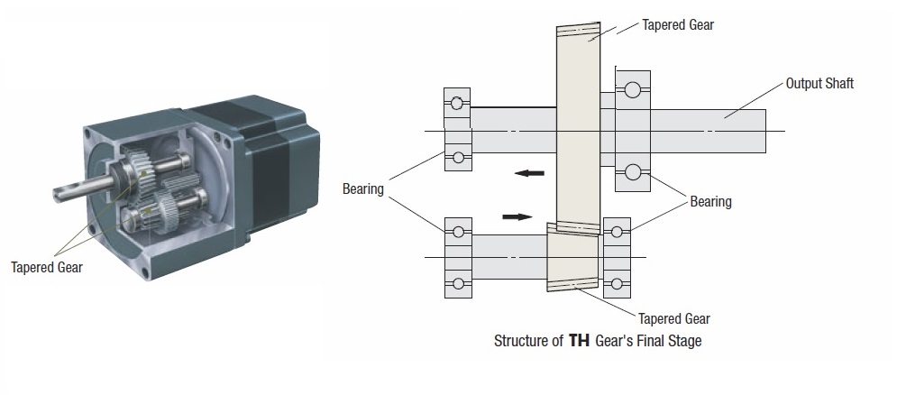
Figure 3: TH gearhead
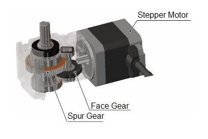
Figure 4: FC gearhead
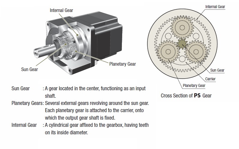
Figure 5: PS gearhead
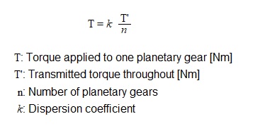
Figure 6: Calculation of the torque applied to a single planetary gear of a planetary gearhead
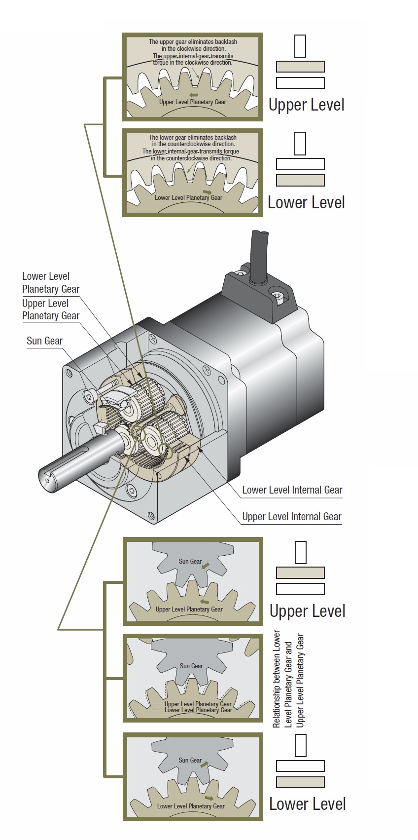
Figure 7: PN gearhead
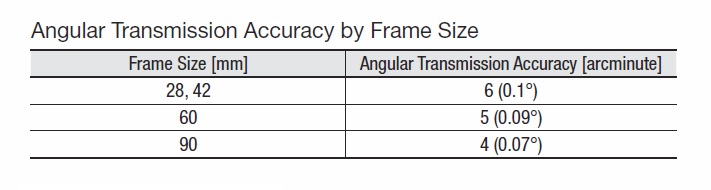
Figure 8: Angular transmission accuracy of PN gearheads
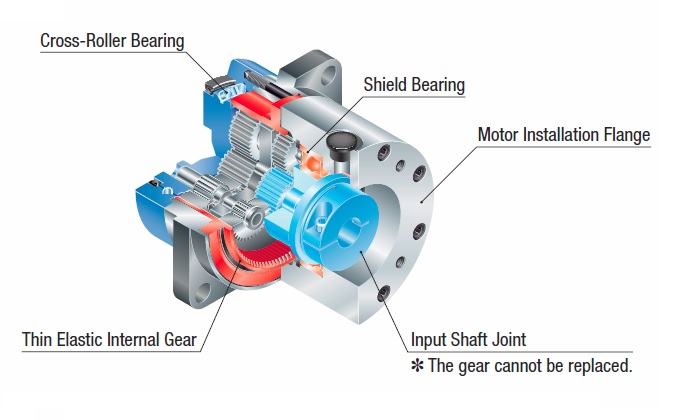
Figure 9: HPG gearhead
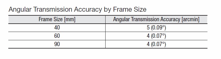
Figure 10: Angular transmission accuracy of HPG gearheads
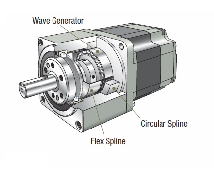
Figure 11: Harmonic gearhead
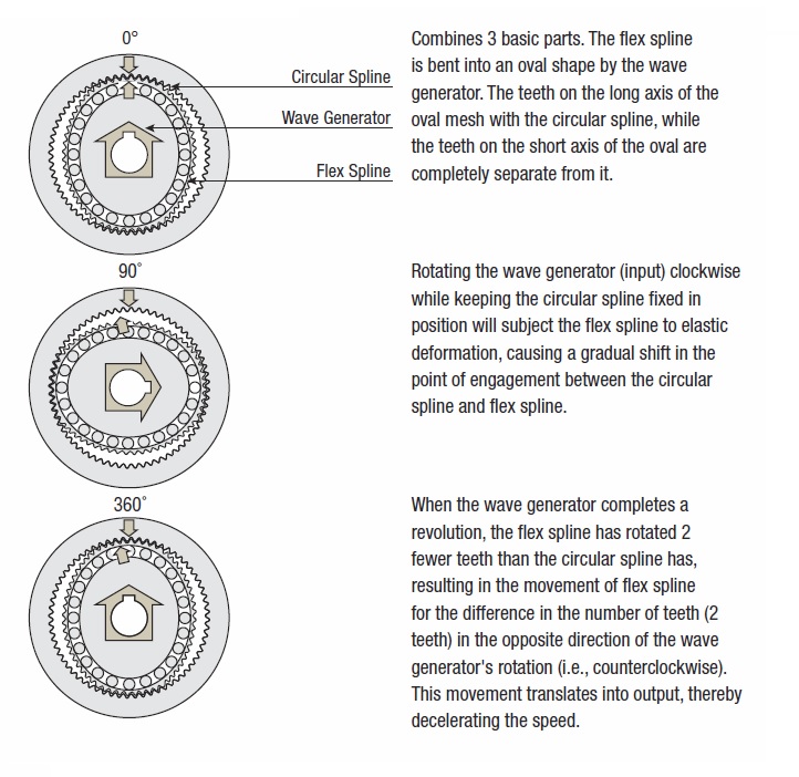
Figure 12: Wave Generator, Flexspline and Circular Spline of a harmonic gearhead
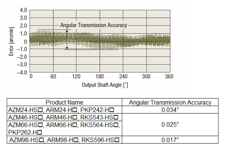
Figure 13: Angular transmission accuracy of harmonic gearheads
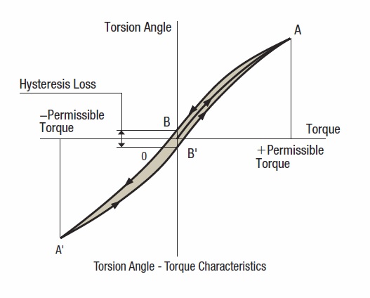
Figure 14: Torque-torsion characteristics
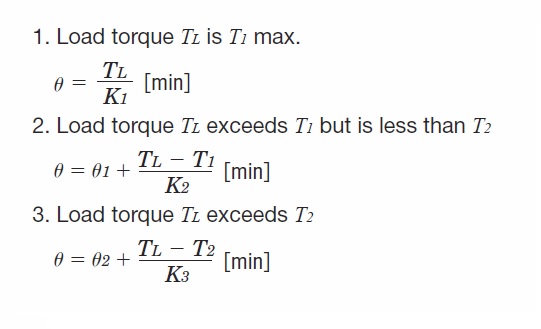
Figure 15: Calculation of the torsion
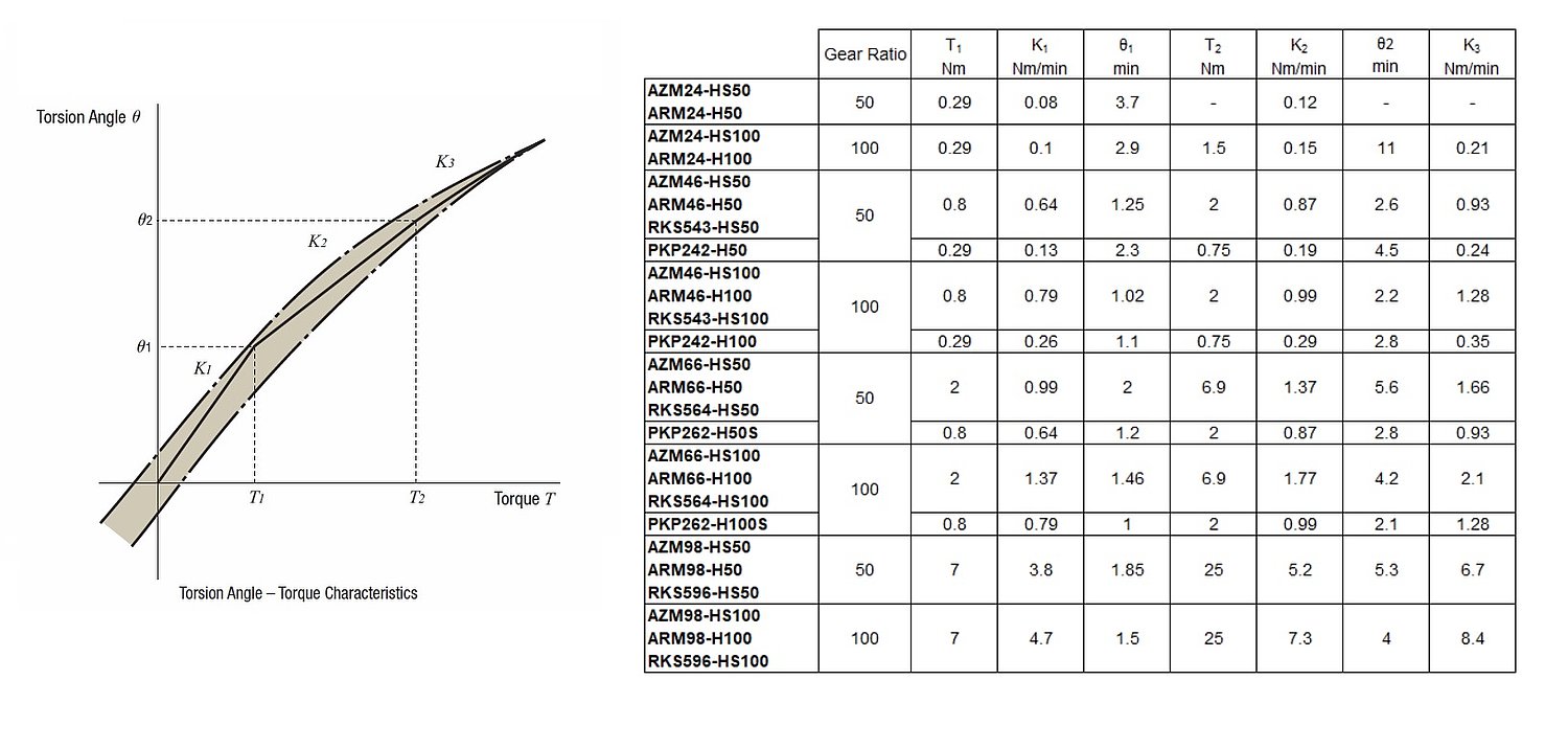
Figure 16: Torsion angles of harmonic gearheads
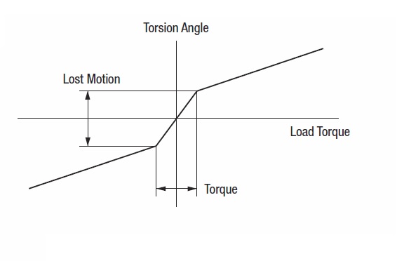
Figure 17: Lost Motion
Structure of fan motors
Axial flow fans (Fig. 1)
These fan motors generate airflow in the direction of their axis of rotation by pressurising air through propellers (blades) in the annular flow path between the cylindrical hub and casing. As the air flow is along the axis of rotation, it has a compact structure. As large air flows can be obtained, axial flow fans are suitable for ventilation cooling applications, such as cooling the entire inside of equipment.
Centrifugal blowers (Fig. 2)
The centrifugal force of the cylindrically arranged impeller (forward-facing blades) creates a swirling flow in a direction almost perpendicular to the axis of rotation. The swirling flow generated is rectified in one direction by the scroll, which also increases the pressure.
The discharge port is narrowed to concentrate the airflow in a fixed direction and is therefore used for localised cooling. The high static pressure also makes it suitable for cooling equipment that is difficult to blow through or for blowing air through ducts.
Cross flow fans (Fig. 3)
Cross flow fans have an impeller similar to a centrifugal blower, but both sides are covered by side plates, so there is no air flow from the axial direction. This results in a through-flow through the impeller. The long cylindrical impeller is used to blow the air, which allows for a wider airflow.
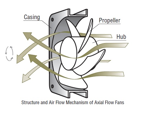
Figure 1: Structure and airflow of axial flow fans
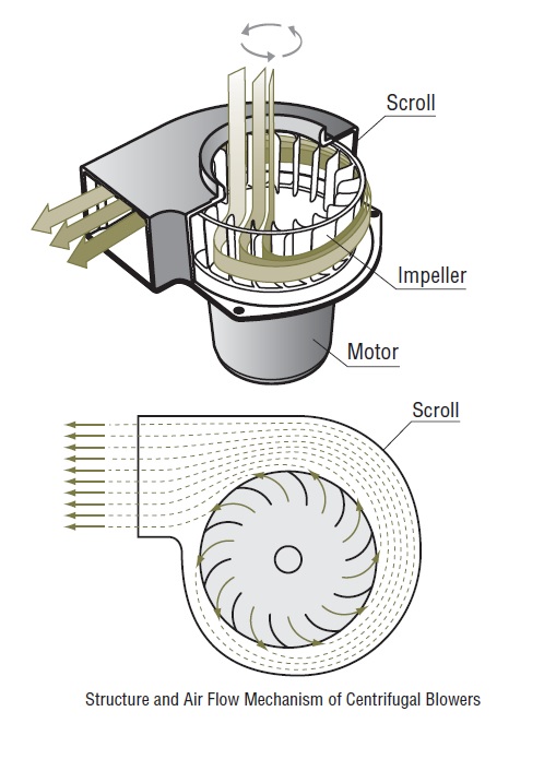
Figure 2: Structure and airflow of centrifugal blowers
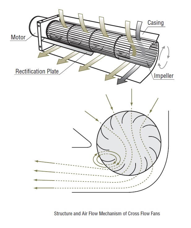
Figure 3: Structure and airflow of cross flow fans
Air flow-static pressure characteristics
Pressure loss
If air is to flow into a certain channel, airflow resistance occurs in that channel in the direction that obstructs the flow.
For example, comparing the figures in Fig.1, the upper device is almost hollow, so the airflow resistance is small and there is little reduction in airflow. However, if there are more obstructions to the airflow, such as in the lower equipment in Fig. 1, the airflow resistance increases and the airflow decreases.
This is very similar to the fact that in current flow, a small impedance results in a large current flow and a large impedance results in a small current flow. This resistance to airflow is the pressure energy that increases the static pressure in the equipment and is called the pressure loss, which is expressed by the equation in Fig. 2.
From the fan motor's point of view, this formula means that the fan motor must have a static pressure that can increase the pressure inside the device by equation (1) P in order to flow a certain air flow Q.
Air flow-static pressure characteristics
The characteristics of a fan motor are generally expressed by the airflow-static pressure characteristic, which shows the relationship between the airflow and the static pressure value when a certain airflow is produced. For example, suppose that the required air flow is Q1 and the pressure loss of the device at that time is P1. In the case of the fan motor characteristic shown in Fig. 3, the fan motor has a static pressure value of P2, which is greater than the required static pressure value P1, so that the required air flow can be obtained sufficiently.
The pressure loss is proportional to the square of the air flow, so if the air flow is to be doubled, it is necessary to select a fan motor that not only has twice the air flow, but also four times the static pressure.
Methods for measuring airflow-static pressure characteristics
There are two methods for measuring the characteristics: the wind tunnel method using a pitot tube and the double chamber method.
The double chamber method is more accurate than the wind tunnel method and is used worldwide, so we use this method.
In addition, our measuring equipment is based on AMCA Standard 210, a fan motor measurement method standard that is widely recognised worldwide. As shown in Fig. 4, this method measures the differential pressure ΔP before and after the nozzle and the pressure Ps in the chamber.
(AMCA: The Air Moving and Conditioning Association)
Our double chamber is the most versatile measuring device, which can be used regardless of whether the fan motor has suction or discharge pipes.
With this method, the velocity of the fluid flowing through the nozzle can be determined from the difference in pressure between chamber A and chamber B. The air flow rate Q can therefore be expressed as the synergistic product of the velocity through the nozzle V, the nozzle area A and the flow coefficient C, as shown in formula (2) in Fig. 5.
Air flow-static pressure characteristics can be measured at various points on the characteristic curve by using an auxiliary blower to control the pressure in chamber B, thereby changing the pressure in chamber A. The system can also be connected to a computer to enable quick and highly accurate measurements.
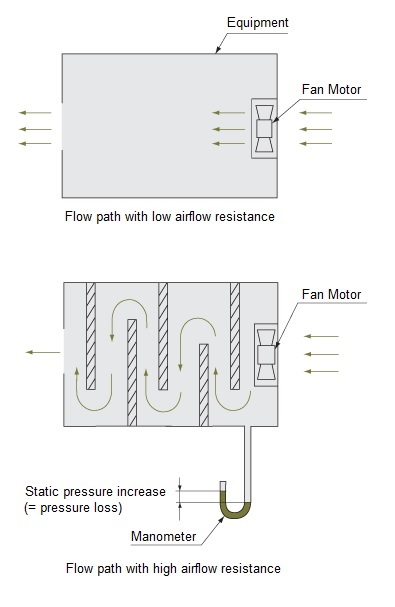
Figure 1: Devices with low and high airflow resistance
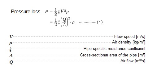
Figure 2: Formula for the calculation of the pressure loss
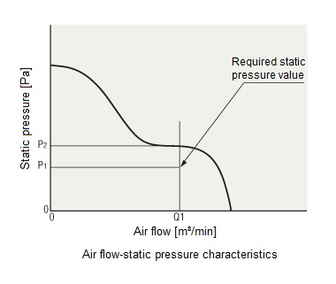
Figure 3: Airflow-Static pressure characteristics
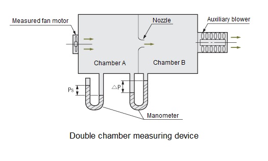
Figure 4: Double chamber measuring device
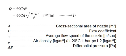
Figure 5: Formula for the calculation of the airflow
Relationship between air flow, static pressure and efficiency
Consideration of pressure loss (Fig. 1)
The most suitable fan motor for a device/equipment depends on the different mounting densities (difficulty of air flow) inside the device.
High mounting density
= High pressure loss
= Internal structures and equipment are laid out in such a way that they resist airflow, making it difficult for air to pass through them.
Low mounting density
= Low pressure loss
= Internal structures and equipment do not create resistance to airflow and allow air to pass through easily.
Efficient cooling can be achieved by using a fan motor with high static pressure when the mounting density is high and a fan motor with high air flow when the mounting density is low.
Fan motor installation and air flow - static pressure characteristics (Fig. 2)
Variation of air flow-static pressure characteristics with installation of peripheral equipment
When fan motors are integrated into devices, peripheral equipment such as finger guards and filters can be fitted to improve the overall safety and reliability of the device. However, peripheral equipment acts as blowing resistance and affects the fan motor characteristics and noise, so this must be taken into account in the selection of fan motors and peripheral equipment.
Fig. 3 shows the pressure loss measured for peripheral equipment for fan motors with a frame size of 119 mm. The filter has the highest loss, while the finger guard has almost no loss.
Taking the fan MU1225S-11 as an example, Fig. 4 shows how the characteristics change when peripheral equipment is attached. The greater the pressure loss of the respective accessory, the more the characteristic curve deteriorates.
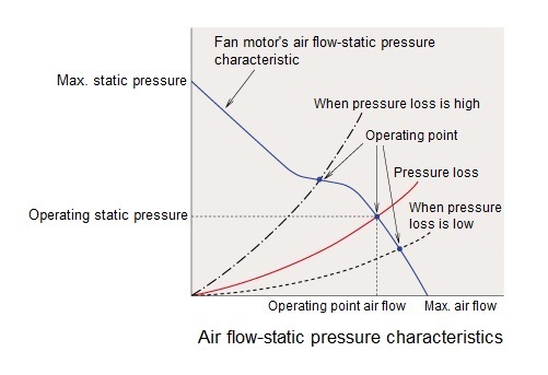
Figure 1: Air flow-Static pressure characteristics
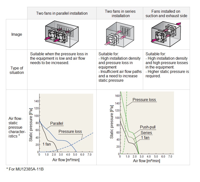
Figure 2: Fan motor installation and air flow-Static pressure characteristics
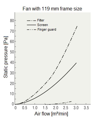
Figure 3: Pressure loss when using peripheral equipment
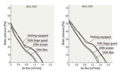
Figure 4: Effect of peripheral equipment on Airflow-Static pressure characteristics
Noise
Noise is a sound that we generally find unpleasant. In the case of fan motors, the rotation of the blades causes a change in air pressure, which generates noise. The greater the change in air pressure, the louder the noise.
Measurement of noise (Fig. 1)
Our noise levels are measured with A-weighted sound pressure levels at 1 m from the suction side of the fan motor (suction centre line).
Composition of noise
Consider the noise level of two fan motors with a noise level of 40 dB each.
As the noise level is displayed in decibels, it cannot be a simple arithmetic sum. To express this, it is necessary to first consider the sound as energy and then calculate the increase in sound pressure.
There is a relationship between sound energy J and sound pressure P. Using the formula shown in Fig. 2, the noise level can be displayed in decibels.
In other words, this formula expresses the noise level in terms of energy J0 and its decibel display. If sound pressure is calculated using this formula, the sound energy is n times higher because there are n cooling fans motors, which can be calculated as shown in Fig. 3.
This means that the increase in noise when operating n fan motors simultaneously is 10log n [dB].
Here there are two fan motors, so n = 2, which means that the noise level will increase by 10log2, or 3 dB, which gives a noise level of 43 dB when two 40 dB fan motors are operated at the same time.
Now consider the noise level for the simultaneous operation of a 40 dB fan motor and a 50 dB fan motor. Again, it is not possible to obtain the combined noise level by arithmetic summing.
Find the difference between the two noise levels: 50 dB – 40 dB = 10 dB
From the 10 dB value of the cross axis read the value of the vertical axis (Fig. 4): 0.4 dB
Add 0.4 to the larger noise level of 50 dB: 50.4 dB
=> 50.4 dB is the noise level for the simultaneous operation.
Adding 40 dB to 50 dB only increases the noise level by 0.4 dB. This means that the noise level is always dominated by the higher value, so if fan motors with different noise levels are operated simultaneously, it is important to find a way to reduce the noise of the noisier fan motor.
Distance and noise
The noise level decreases with distance from the sound source.
The distance attenuation of the noise level can be expressed in the following formula.
SPL2 = SPL1 – 20log r2/r1
SPL2: Noise level at distance r2
SPL1: Noise level at distance r1
Let's look at the noise level of a fan motor that is 40 dB at 1 m from the suction side, measured at 2 m.
r2=2 m
r1=1 m
SPL1=40 dB
SPL2 = 40 – 20log 2/1
= 34 [dB]
At a distance of 2 m, this means a 6 dB drop.
The formula above, 20log r2/r1, shows the ratio of the two distances, so the same can be said for a comparison between distances of, say, 3 m and 6 m. This means that if the noise level at a certain distance is known, it is possible to estimate the noise level at a different distance.
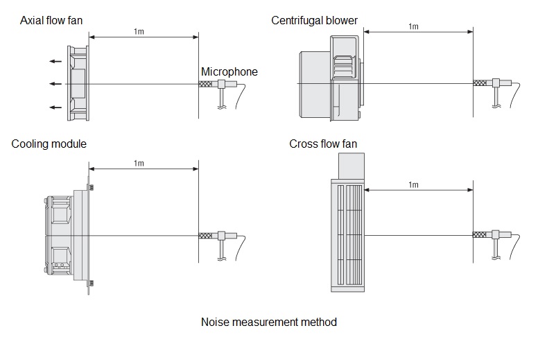
Figure 1: Noise measurement
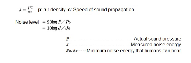
Figure 2: Formula for calculating the noise level
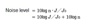
Figure 3: Formula for calculating the noise level when using several fans
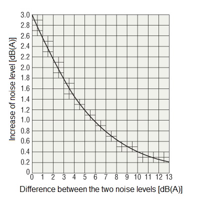
Figure 4: Characteristics for determining the increase of noise level
Capacitor for fans
In capacitor start and run motors, the main winding and the auxiliary winding are wound on different polar axes by 90° at an electrical angle. A capacitor is connected in series with the auxiliary winding and acts to advance the phase of the current in the auxiliary winding.
Motors employ vapour-deposited electrode capacitors recognized by UL. This type of capacitor uses a metal vapour-deposited plastic film as a component and is also commonly referred to as an SH (Self Healing) capacitor because of its self-healing action.
Capacitance
If the capacitance of the capacitor is wrong, the vibration and heat generation of the cooling fan motor may be abnormally high, or operation may become unstable due to loss of torque. Always use the capacitor included with the fan motor. Capacitance of capacitors is expressed in units of µF (microfarad).
Rated voltage
If the capacitor is used above the service rating voltage, it may be damaged, resulting in smoking or ignition. Always use the capacitor included with the fan motor. The rated voltage of the capacitor is expressed in units of volts (V).
The rated voltage of the capacitor is displayed on the surface of the capacitor case. Note that this is different from the rated voltage of the fan motor itself.
Rated lifetime
Rated lifetime time is the minimum lifetime of the capacitor when operating at its rated load, rated voltage, rated temperature and rated frequency. 40,000 hours is the reference. If the capacitor is damaged at the end of its lifetime, smoking or ignition may result. It is recommended to replace the capacitor after the rated conduction time rating as a reference.
In the event of an abnormality in the capacitor, please consider a separate protective measure to ensure that the equipment is not affected.
Capacitor with safety mechanism
Types with a functional safety mechanism are available which safely disconnect the capacitor from the circuit in the event of a dielectric breakdown and prevent it from smoking or igniting. Our products use UL recognised capacitors with safety mechanisms that satisfy the UL 810 failure current test of 10,000 A.
Overheat protection device for fans
If a fan motor in operation status is locked rotor condition due to an overload, or if the ambient temperature rises rapidly, or if the input increases for some cause, the temperature of the fan motor will rise rapidly. If left unattended in this state, the insulation performance inside the fan motor will deteriorate, shortening its lifetime or, in extreme cases, even burning out the windings and causing a fire. The following overheat protective devices are provided to protect fan motors from such heat abnormalities.
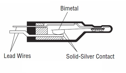
Thermal protector (automatic return type)
The structure of the thermal protector is shown in the diagram below.
Thermal protectors are bimetal systems and use pure silver contact points, which have the lowest electrical resistance of any metal and the second highest heat conduction after copper.
Operating temperature of thermal protector
Open: 120±5°C (Some models have different operating temperatures)
Close: 76±20°C (Some models have different operating temperatures)
(The fan motor winding temperature when the thermal protector is operating is slightly higher than the operating temperatures listed above.)
Impedance protected
Impedance protected fans are designed to increase the impedance of the fan motor windings so that even if the fan motor is locked, the increase in current (input) is kept small and the temperature rise does not exceed a certain value.
Built-in burnout prevention circuit
DC fans are equipped with a burnout prevention circuit that interrupts the energisation of the windings or limits the current when the rotor is locked.